background image

2BC/D-1

1-6-18

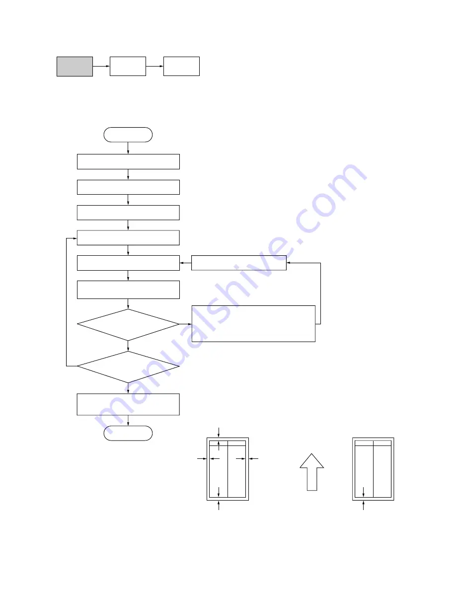
(6-4) Adjusting the margins for printing

Make the following adjustment if the margins are not correct.

Caution

Check the copy image after the adjustment. If the margins are still incorrect, perform the above adjustments in
maintenance mode.

Procedure

Figure 1-6-35

U402

U403

(P. 1-6-38)

U404

(P. 1-6-72)

Yes

No

Start

Enter maintenance mode.

Enter “402” using the numeric keys.

Press the start key.

Press the start key to output a test 

pattern using A3/11" 

×

 17" paper.

Press the start key.

The new setting is stored.

Setting range (initial setting)

LEAD: 0 – +10.0 (

3.5

)

A: –5.0 – +10.0 (

2.5

)

C: –5.0 – +10.0 (

2.5

)

TRAIL: –5.0 – +10.0 (

6.4

)

TRAIL (DUP): –5.0 – +10.0 (

6.4

)

Changing the value by 1 moves the 
margin by 0.1 mm for all.

Select the items to be adjusted.

Are the margins correct?

Change the setting. 
Increasing the value using the cursor up 
key makes the margin winder. 
Decreasing the value using the cursor 
down key makes the margin narrower.

Press the interrupt key.

LEAD: Printer leading edge margin
A: Printer left margin
C: Printer right margin
TRAIL: Printer trailing edge margin 
TRAIL (DUP): Printer trailing edge margin for 

 duplex copying (second face)

Yes

No

Press the stop/clear key to 

exit maintenance mode.

End

Proceed to 

another mode?

Ejection direction

(reference)

Printer trailing edge margin 
for duplex copying 

(6 

±

 2.5 mm)

Printer leading edge margin

(6 

±

 2.5 mm)

Printer 

left margin

(6 

±

 2.0 mm)

Printer 
right margin

(6 

±

 2.0 mm)

Printer trailing edge margin

(6 

±

 2.5 mm)

Duplex copy mode 

(second face, A3/11" 

×

 17")

Normal copy mode 

(A3/11" 

×

 17")

Summary of Contents for KM-4530

Page 1: ...SERVICE MANUAL Published in Apr 02 2BC70761 Revision 1 KM 4530 5530...

Page 2: ...URER DISPOSE OF USED BATTERIES ACCORDING TO THE MANUFACTURER S INSTRUCTIONS ATTENTION IL Y A DANGER D EXPLOSION S IL Y A REMPLACEMENT INCORRECT DE LA BATTERIE REMPLACER UNIQUEMENT AVEC UNE BATTERIE DU...

Page 3: ...sonnel to ensure the safety of their customers their machines as well as themselves during maintenance activities Service personnel are advised to read this booklet carefully to familiarize themselves...

Page 4: ...mpliance with warning messages using this symbol WARNING Serious bodily injury or death may result from insufficient attention to or incorrect compliance with warning messages using this symbol CAUTIO...

Page 5: ...or dusty place This may cause fire or electric shock Do not install the copier near a radiator heater other heat source or near flammable material This may cause fire Allow sufficient space around th...

Page 6: ...clean Dirt on them can cause abnormally high temperatures Do not remove the ozone filter if any from the copier except for routine replacement 2 Precautions for Maintenance WARNING Always remove the...

Page 7: ...t all the caution labels that should be present on the machine according to the instruction handbook are clean and not peeling Replace with new ones if necessary Handle greases and solvents with care...

Page 8: ...counter option 1 3 16 1 3 4 Installing the multi simple finisher option 1 3 18 1 3 5 Installing the side deck option 1 3 24 1 3 6 Installing the Network scanner kit option 1 3 28 1 3 7 Installing the...

Page 9: ...er scatters at the leading edge of the image 1 5 40 1 1 5 4 Electrical problems 1 5 41 Copier 1 5 41 1 The machine does not operate when the main switch is turned on 1 5 41 2 The image formation motor...

Page 10: ...The message requesting paper to be loaded is shown when paper is present in drawer 2 1 5 50 58 The message requesting paper to be loaded is shown when paper is present in drawer 3 1 5 50 59 The messag...

Page 11: ...ching and refitting the exposure lamp 1 6 21 2 Detaching and refitting the scanner wires 1 6 22 2 1 Detaching the scanner wires 1 6 22 2 2 Refitting the scanner wires 1 6 25 3 Detaching and refitting...

Page 12: ...Adjusting the DF magnification 1 6 68 4 Adjusting the DF original center line 1 6 69 5 Adjusting the scanning start position when the DF is used 1 6 70 5 1 Adjusting the DF leading edge registration...

Page 13: ...7 7 DF switches and sensors 2 2 8 8 DF motors 2 2 9 9 DF clutches and solenoids 2 2 10 2 3 Operation of the PCBs 2 3 1 Power source PCB 2 3 1 2 3 2 Main PCB 2 3 6 2 3 3 Engine PCB 2 3 11 2 3 4 Scanner...

Page 14: ...cation in memory copy mode A4 11 81 2 45 copies min A4R 81 2 11 32 copies min A3 11 17 24 copies min B4 257 364 mm 81 2 14 28 copies min B5 45 copies min B5R 36 copies min When the DF is used at 100 m...

Page 15: ...gas lamp Dimensions 680 W 804 D 1141 H mm 2613 16 W 3111 16 D 4415 16 H Weight Approx 180 kg 396 lbs Floor requirements 1331 mm W 804 D mm 527 16 W 3111 16 D Functions 1 Self diagnostics 2 Preheat 3...

Page 16: ...memory copy mode A4 11 81 2 55 copies min A4R 81 2 11 38 copies min A3 11 17 28 copies min B4 257 364 mm 81 2 14 32 copies min B5 55 copies min B5R 40 copies min When the DF is used at 100 magnificati...

Page 17: ...4 Original size detection 5 Automatic paper selection 6 Automatic magnification selection 7 Zoom mode 8 XY zoom mode 9 Preset zoom mode 10 Document management functions 11 Output management functions...

Page 18: ...Original table Original insert guides DF original reversing cover Original set indicator Original eject table DF opening closing lever Ejection extension Deck paper conveying unit Handles for transpor...

Page 19: ...key indicator lamp 6 Management key 7 default setting key 8 Numeric key 9 Touch panel 0 Brightness adjustment control dial Copier key indicator lamp Printer key indicator lamp Scanner key indicator la...

Page 20: ...ging section 3 Optical section 4 Developing section 5 Transfer and paper conveying section 6 Cleaning section 7 Charge erasing section 8 Fixing section 9 Feedshift and eject section 0 Duplex section D...

Page 21: ...2BC D 1 1 8 1 1 4 Drive system 1 Drive system 1 optical section Figure 1 1 4 1 Scanner motor pulley 2 Scanner drive belt 3 Scanner drive pulley 4 Scanner wire drum 5 Scanner wire 6 Scanner wire pulley...

Page 22: ...belt 5 Gear 32 6 Feed gear 42 7 Registration clutch gear 8 Feed gear 27 9 Feed low clutch 1 gear 34 0 Feed gear 49 65 Paper feed motor gear Paper feed gear 68 Paper feed drive pulley 29 52 Idle pulley...

Page 23: ...le gear 26 5 Paper feed clutch 3 gear 6 Feed clutch 5 gear 7 Deck paper feed drive pulley 8 Tension pulley 20 9 Deck paper feed drive belt 0 Feed gear 49 65 Deck drive motor gear Pulley 20 Deck convey...

Page 24: ...age formation motor gear 7 Gear 63 35 8 Drum pulley 51 9 Tension pulley 0 Drum drive belt Gear 19 Registration gear 24 Registration clutch gear Pulley 40 28 Cleaning drive belt Gear 26 Gear 30 Drum Fi...

Page 25: ...ject drive gear 6 Fixing gear 35 7 Fixing pulley 34 8 Fixing gear 63 32 9 Paper conveying motor gear 0 Fixing drive belt Duplex gear 45 30 Duplex gear 29 42 Gear 18 26 Fixing joint gear Heat roller ge...

Page 26: ...Paper conveying pulley 40 4 Paper conveying drive belt 5 Paper conveying tension pulley 6 Paper conveying pulley 20 7 Paper conveying pulley 20 8 Duplex registration gear 20 30 9 Clutch gear 26 0 Fron...

Page 27: ...forwarding pulley 18 7 Tension pulley 8 Original feed drive belt 9 DF forwarding belt 0 DF registration pulley 28 18 Idle gear 15 Idle gear 20 Switch back gear 18 DF registration drive belt Gear 22 35...

Page 28: ...lation location Avoid direct sunlight or bright lighting Ensure that the photoconductor will not be exposed to direct sunlight or other strong light when removing paper jams Avoid extremes of temperat...

Page 29: ...developing unit Adjusting the fixing pressure Adding toner Setting the cleaning blade Applying toner to the cleaning blade run of maintenance mode U160 Exit maintenance mode Start Installing the drum...

Page 30: ...r right pad 6 Skid 7 Hinge joints 8 Eject pad 9 Drawer spacer 0 Drawer spacer Drawer spacer Upper case Outer case Supports Bar code labels Power code Eject tray Drum set Tray spacer OFF label Size pal...

Page 31: ...emove the piece of tape that secures the front cover 6 Open the front cover and remove the piece of tape that secures the DF Removing the securing tape and the spacer Figure 1 3 2 Figure 1 3 4 7 Pull...

Page 32: ...s Light source unit 2 pin Figure 1 3 5 Figure 1 3 6 9 Pull out drawer 3 remove the spacer 10 Pull out drawer 4 remove the spacer The lift or the guide may be deformed or damaged when turns the main sw...

Page 33: ...ase lever to pull out the image formation unit 1 Open the front cover pull out the hinge shaft to remove and remove the front cover Figure 1 3 8 Figure 1 3 10 Figure 1 3 9 Front cover Hinge shaft Pape...

Page 34: ...ise the shutter a little and slide it toward the front side of the machine 6 Turn the auxiliary toner hopper to the right of the machine 7 Hold the front and the rear of the developing unit and remove...

Page 35: ...ly to stir the developer 3 While turning the developing magnet roller gear and the developing spiral cam in the directions indicated by the arrows alternately add developer uniformly into the developi...

Page 36: ...ositioning plate and the rear drum positioning plate with a screw each Fit the drum so that the side with the thin shaft of the drum flange is placed on the front side of the machine and the side with...

Page 37: ...ressure 3 Open the eject cover 4 Turn the fixing press nuts on the front and rear of the fixing unit clockwise to adjust the fixing pressure 5 Close the eject cover 6 Push the paper conveying unit int...

Page 38: ...Start key The drum will be covered with toner and driving will stop automatically 1 Open and close the front cover use the numeric keys to enter 001 and press the Start key The machine will exit from...

Page 39: ...hake the toner bottle up and down and from side to side approximately 10 times 2 Hold a new toner bottle upside down and tap the bottom approximately 10 times Figure 1 3 22 Figure 1 3 24 Figure 1 3 23...

Page 40: ...al pin at the opening for toner replenishment 5 While pushing down the toner bottle turn it 90 clockwise 7 To drop toner completely tap the side of the toner bottle approximately 10 times 6 Wait until...

Page 41: ...9 Close the operation right cover Figure 1 3 28 Figure 1 3 29 Drawer heater relay cable CN12 Power souce PCB Drawer heater relay cable 1 Remove the lower rear cover 2 Connect the connector of the dra...

Page 42: ...3 14 2BC D 1 Figure 1 3 30 Make test copies 1 Set paper in a drawer and execute a test copy run Completion of the machine installation OFF label 4 Attach the OFF label to the OFF side of the main swit...

Page 43: ...ments Setting Auto rotation copy Sort copy Setting the number of sheets to enter stacking moce during sort operation Switching the paper ejection mode Switching between duplex simplex copy mode Settin...

Page 44: ...00 One 1 M4 6 chrome TP A screw P N B4104060 One 1 M3 8 bronze binding screw P N B1303080 One 1 M4 30 bronze binding screw P N B1304300 Two 2 M3 6 bronze flat head screws P N B2303060 One 1 M3 bronze...

Page 45: ...d parts 8 Fit the key counter cover with the key counter assembly inserted to the key counter cover retainer on the machine 9 Insert the key counter into the key counter assembly 10 Turn the main swit...

Page 46: ...Figure 1 3 34 Figure 1 3 35 Figure 1 3 36 2 Attach the finisher connecting plate to the copier left cover and then hold them together with the two M4 12 binding screws 3 Attach the connecting sponge t...

Page 47: ...ise the connecting lever at the bottom of the finisher Fitting the projection into the hole lowers the hooks 6 Remove the screw and pull out the connecting rail at the upper part of the finisher Figur...

Page 48: ...te is inserted into the hole at the rear of the finisher and the two short pins into the holes on the connecting rail 9 Make sure that the finisher is securely joined with the copier Then push the con...

Page 49: ...wn with the screw removed in step Figure 1 3 41 Figure 1 3 42 Connecting lever Separate retainers Blue screws Intermediate tray Blue screws 11 Remove the four blue screws locking each of the two separ...

Page 50: ...iate tray and then remove the four strips of fixing tape 15 Insert a stapler cartridge into each of the staplers and of the intermediate tray Press on the cartridges until they are securely locked Not...

Page 51: ...re the main tray with two pins 18 Attach the sub tray to the finisher by inserting the projections at the front and back of the sub tray into the holes of the finisher For the multi finisher only 19 A...

Page 52: ...right front lower cover followed by the cover Figure 1 3 48 Figure 1 3 49 Figure 1 3 50 Bypass table Right cover Developing duct cover 2 pin connector Middle right cover Right front lower cover Pin P...

Page 53: ...d remove from the copier by raising the cover in the direction of the arrow 9 Attach the upper merge guide with two M4 8 TP P tight screws Note With the 55 cpm copier be sure to use the merge guide wi...

Page 54: ...middle right cover and right cover Note When reattaching the developing unit duct cover be sure to reconnect the 2 pin connector to the cooling fan Figure 1 3 54 Upper merge guide Lower merge guide M3...

Page 55: ...nter of the scale located at the base of the copier using the two M4 6 TP A chromate screws 16 When the side deck is installed on the copier connect the deck signal cable to the connector on the copie...

Page 56: ...the middle rear cover 4 Remove the four screws and remove the upper sequence cover 5 Remove the two screws and remove the cover 6 Firmly push connector CN1 on the scanner board all the way into connec...

Page 57: ...he Ethernet cable to the core by winding it one turn around the core 10 Fit the Ethernet cable described in step 9 to the Ethernet cable connector 11 Secure the Ethernet cable to the lower left screw...

Page 58: ...1 3 65 1 3 7 Installing the Printer kit option Preparation 1 Remove two screws and take off the cover 2 Push the printing system all the way in along the rails and fasten it to the controller box with...

Page 59: ...sh the printer network kit all the way in along the rails and fasten it to the controller box with two screws Install the optional hard disk 5 Remove two screws and take off the cover 6 Push the hard...

Page 60: ...M 8 Remove the printing system and insert the optional memory DIMM firmly into either of the memory slots Push the DIMM firmly into the slot so that the two hooks one hook at each end of the slot snap...

Page 61: ...e lower rear cover and then the cover 4 Remove the eleven screws securing the upper and lower sequence covers and then the covers 5 Remove the two screws securing the interface mounting plate and then...

Page 62: ...tion 8 Insert CN1 on the assembly relay PCB into CN5 on the main PCB of the copier 9 Secure the interface PCB with an M4 6 binding screw 10 Insert the 2 pin connector on the S BOX wire into 2 pin conn...

Page 63: ...he interface PCB to the interface mounting plate with two M2 6 5 brass binding screws 13 Refit the upper and lower sequence covers the lower rear cover the middle rear cover and the middle rear C cove...

Page 64: ...nter the management code Make weekly timer settings page 1 4 2 Press the Copy default key Press the Close key Enter the management code Make copy default settings page 1 4 3 Output the setting list pa...

Page 65: ...unter by ID code key 2 View copy counts using the cursor up down keys 3 Press the Close key 4 Press the Close key Print management list 1 Press the Print the list key If A4 11 81 2 paper is present th...

Page 66: ...be selected Default drawer Sets the drawer to be selected in cases such as after the reset key is pressed 1 Select Default drawer Default cassette and press the Change key 2 Select priority drawer Dr...

Page 67: ...to 3 Margin width Sets the default setting of the margin width for the margin copying 1 Select Default margin width and press the Change key 2 Press the up down right and left cursor keys to set the...

Page 68: ...whether All types of paper or Feed same paper type is selected 1 Select Auto drawer switching Auto cassette switching and press the Change key 2 Select On or Off 3 Select All types of paper or Feed s...

Page 69: ...nergy print box 1 Press the Box editting key 2 Select the desired box 3 Press the Change key 4 Enter the box name 5 Press the End key 6 Press the Yes key 7 Press the Close key 8 Press the Job cancel k...

Page 70: ...key 2 Press the Close key 9 Report Outputs the setting reports 1 Press the Print form key 2 Select the report Copy report Option report Counter report Machine report 10 Language Switches the language...

Page 71: ...er 001 using the cursor up down keys or numeric keys and press the start key Enter the maintenance item number using the cursor up down keys or numeric keys The selected maintenance item is run Press...

Page 72: ...Duplex forwarding clutch off timing 160 Duplex forwarding clutch off timing 110 for 11 17 copy paper only Duplex reversing clutch on timing 50 Duplex reversing clutch off timing 132 U051 Adjusting the...

Page 73: ...Developing bias step control final voltage 207 Developing bias step control initial voltage 52 Transfer control voltage for simplex copying 210 Transfer control voltage for duplex copying 210 Separati...

Page 74: ...t operation Side feed U235 Setting output tray initialize mode HP ON U240 Checking the operation of the finisher U241 Checking the operation of the switches of the finisher U243 Checking the operation...

Page 75: ...ting margins for scanning an original from the DF U407 Adjusting the leading edge registration for memory image printing 0 U504 Initializing the scanner NIC U505 Setting Data Base Assistant ON U901 Ch...

Page 76: ...2BC D 1 1 4 13 This page is intentionally left blank...

Page 77: ...screen for selecting an item The screen for selecting a maintenance item No is displayed U001 Exiting the maintenance mode Description Exits the maintenance mode and returns to the normal copy mode Pu...

Page 78: ...e number is set and the screen for selecting a maintenance item No is displayed Completion To exit this maintenance item without changing the current setting press the stop clear key The screen for se...

Page 79: ...o control the paper feed pulley remove all the paper in the drawers or the drawers With the paper present the paper feed pulley does not operate 6 Press the start key The operation starts Copy operati...

Page 80: ...el It is displayed in reverse 3 Press the start key All data in the backup RAM is initialized and the original settings for inch specifications are set When initialization is complete the machine auto...

Page 81: ...een for executing is displayed 2 Press EXECUTE on the touch panel It is displayed in reverse 3 Press the start key to initialize the hard disk The EXECUTE display flashes during initializing Initializ...

Page 82: ...itch 2 PFSW2 FEED C SW Paper feed switch 3 PFSW3 FEED D SW Paper feed switch 4 PFSW4 FEED E SW Paper feed switch 5 PFSW5 FEED F SW Paper feed switch 6 PFSW6 FEED DK 2SW Deck paper conveying switch 2 D...

Page 83: ...ration clutch RCL DUP FWD Duplex forwarding clutch DUPFWDCL DUP REV Duplex reversing clutch DUPREVCL Completion Press the stop clear key The screen for selecting a maintenance item No is displayed U03...

Page 84: ...s set Completion Press the stop clear key at the screen for adjustment The screen for selecting a maintenance item No is displayed U037 Checking fan motor operation Description Applies power to each f...

Page 85: ...creasing it makes the image shorter in the auxiliary scanning direction POLYGON MOTOR Increasing the setting makes the image longer in the main scanning direction and shorter in the auxiliary scanning...

Page 86: ...ensity in text text and photo or photo mode Purpose Used when the entire image appears too dark or light Method Press the start key The screen for executing is displayed Setting 1 Change the setting u...

Page 87: ...de Completion Press the stop clear key at the screen for adjustment The screen for selecting a maintenance item No is displayed U064 Adjusting the CCD level Description Adjusts the CCD level Purpose T...

Page 88: ...y Operating conditions Setting range ZOOM Magnification 25 to 400 SIZE Original size See below LAMP On and off of the exposure lamp 0 off or 1 on Original sizes for each setting in SIZE Setting Paper...

Page 89: ...ARGIN DF scanning right margin DF D MARGIN DF scanning trailing edge margin If a problem occurs during auto adjustment DATA XX XX is replaced by an error code is displayed and operation stops Should t...

Page 90: ...L To check the drum quality 256 LEVEL To check resolution reproducibility in printing 1 DOT LINE To check fine line reproducibility To adjust the position of the laser scanner unit lateral squareness...

Page 91: ...nd rear When scanning is performed after shading there should be no difference between respective values Any differences between the values at machine front and rear indicates that scanner problem cau...

Page 92: ...adjustment starts When adjustment is complete each adjusted value is displayed Display Description SCAN CENTER Scanner center line SCAN TIMING Scanner leading edge registration SUB SCAN Scanner auxil...

Page 93: ...usted The selected item is displayed in reverse 2 Adjust the setting using the cursor up down keys Display Description Setting range Initial setting DARKER Change in density when manual density is set...

Page 94: ...the screen for selecting an item press the stop clear key Setting 1 Select an item to be set Display Description Setting range Initial setting LEVEL Detection sensor threshold value 0 to 255 170 WAIT...

Page 95: ...en for selecting an item select one from MC ON MC ON OFF or LASER ON OFF on the touch panel The selected operation starts 2 To stop operation press the stop clear key Setting the grid control voltage...

Page 96: ...screen for selecting an item 2 Select an item to be set Display Description Setting range Initial setting TC DATA Transfer control voltage for simplex copying 0 to 255 210 TC DATA DUP Transfer control...

Page 97: ...value is set Completion Press the stop clear key The screen for selecting a maintenance item No is displayed U110 Checking clearing the drum count Description Displays the drum counts for checking cl...

Page 98: ...key The screen for selecting a maintenance item No is displayed U114 Selecting AC mode Description Sets separation control for A3 B4 A4R 11 17 11 15 and 81 2 14 sizes Purpose To change the setting to...

Page 99: ...00 INTERVAL M Correction interval for effective 0 to 600000 1000 potential correction TARGET Effective correction target value 0 to 999 550 RUN To run the test operation 3 Press the start key The valu...

Page 100: ...1 4 35 2BC D 1 This page is intentionally left blank...

Page 101: ...57 Clearing the developing count U158 Resetting the toner feed start level and toner empty detection Completion Press the stop clear key after initial setting is complete The screen for selecting a ma...

Page 102: ...e sure to drive the motor for only a few seconds Method 1 Press the start key The screen for selecting an item is displayed 2 Select the item to be operated The selected item is displayed in reverse T...

Page 103: ...ner loading at the rate of one time every 30 sheets ON Toner loading performed in MODE1 OFF Toner loading not performed in MODE1 MODE2 Toner loading at the rate of one time per sheet between two sheet...

Page 104: ...wn keys Description Setting range Initial setting Toner control level 0 to 255 102 Increasing the setting makes the toner density lower 3 Press the start key The time is set Setting for the toner empt...

Page 105: ...loping count for checking clearing or changing a figure which is used as a reference when correcting the toner control It is automatically cleared when U130 is executed Purpose To check the developing...

Page 106: ...Completion Press the stop clear key at the screen for adjustment The screen for selecting a maintenance item No is displayed U162 Stabilizing fixing forcibly Description Stops the stabilization fixin...

Page 107: ...rns off Display Description MAIN Fixing heater M FH M SUB Fixing heater S FH S Completion Press the stop clear key when fixing motors M and S are off The screen for selecting the maintenance item No i...

Page 108: ...the touch panel after it is replaced Method 1 Press the start key The screen for executing is displayed and the key displayed at the upper left of the touch panel flashes 2 Press on the center of the...

Page 109: ...tion Press the stop clear key when the operation stops The screen for selecting a maintenance item No is displayed U204 Setting the presence or absence of a key card or key counter Description Sets th...

Page 110: ...1 When all the keys in that line are pressed and if there are any LEDs corresponding to the keys in the line on the immediate right the top LED in that line will light 4 When all the keys on the opera...

Page 111: ...out changing the current setting press the stop clear key at the screen for the year setting The screen for selecting a maintenance item No is displayed U212 Setting the deck lift operation Descriptio...

Page 112: ...r MTEM JTRAY MOTOR Multi job tray elevation motor MJTEM BRA A SOL Feedshift solenoid A FSSOLA BRA B SOL Feedshift solenoid B FSSOLB BRA C SOL Feedshift solenoid C FSSOLC PUNCH P SOL Punch solenoid PUN...

Page 113: ...mitting intercepting sensor MTPUSDLES MTPUSDLIS MTRAY PUSH Paper holder detection sensor PHDS MTRAY OVER1 Main tray load 1000 detection sensor MTLDS 10 MTRAY OVER2 Main tray load 1500 detection sensor...

Page 114: ...o turn each motor off press the stop clear key Completion Press the stop clear key when operation stops The screen for selecting a maintenance item No is displayed U244 Checking the DF switches Descri...

Page 115: ...ected 51 2 81 2 81 2 14 81 2 11 11 17 11 15 11 81 2 000 49 664 50 176 61 440 61 952 103 936 104 448 139 264 139 776 146 432 146 994 197 120 197 632 197 720 223 232 256 For example if any value between...

Page 116: ...r selecting a maintenance item No is displayed U247 Setting the paper feed device Descrioption Drives each motor of the optional side deck Purpose To check the operation of the optional side deck Meth...

Page 117: ...f the amount of slack in the paper in punch mode PUNCH TIMING TURN Adjustment of the amount of slack in the paper at reversed paper ejection in punch mode PUNCH COUNT Punch hole scrap count display SA...

Page 118: ...nt of slack larger If paper jams or is Z folded frequently decrease the setting to make the amount of slack smaller Changing the value by 1 changes the amount of slack by 1 0 mm 4 Press the start key...

Page 119: ...item press the stop clear key Setting the center folding position correction of number of sheets of a batch 1 Select SADDLE ADJUST 2 on the screen for selecting an item 2 Select the item to be set 3 C...

Page 120: ...DLE ADJUST 2 therefore need not be changed in principle Only if any problem occurs at the center folding position depending on the number of sheets of a batch adjust SADDLE ADJUST 2 Completion To exit...

Page 121: ...press the stop clear key The screen for selecting a maintenance item No is displayed U251 Checking clearing the maintenance count Description Displays clears and changes the maintenance count Purpose...

Page 122: ...maintenance items below To change the initial settings in those items be sure to run maintenance item U021 after changing the destination Initial setting according to the destinations Maintenance Tit...

Page 123: ...screen for selecting a maintenance item No is displayed U255 Setting auto clear time Description Sets the time to return to initial settings after copying is complete Purpose To be set according to f...

Page 124: ...the start key The screen for selecting an item is displayed Setting 1 Select ON or OFF The selected item is displayed in reverse Display Description ON Auto preheat energy saver function on OFF Auto...

Page 125: ...300 copies 200 the toner level sensor before indicating toner empty The setting can be changed by 100 per step 2 Press the start key The value is set and the screen for selecting a maintenance item No...

Page 126: ...secondary paper feed starts EJECT When the paper is ejected Initial setting EJECT 2 Press the start key The setting is set and the screen for selecting a maintenance item No is displayed Completion To...

Page 127: ...key The setting is set and the screen for selecting a maintenance item No is displayed Completion To exit this maintenance item without changing the current setting press the stop clear key The scree...

Page 128: ...plex copy mode Method 1 Press the start key The screen for selecting an item is displayed 2 Select an item to be set Display Description MODE0 Circulation of five sheets MODE1 Circulation of four shee...

Page 129: ...tting for the output mode under user simulation Purpose To be set as required according to the number of copies the user makes Method Press the start key The current setting is displayed Setting 1 Cha...

Page 130: ...DD Purpose To set data according to the manufacturer and type of the new HDD after replacement Method Press the start key The screen for selecting an item is displayed Setting 1 Change the setting usi...

Page 131: ...n Purpose According to user request sets or cancels restriction on the number of sheets Method 1 Press the start key The screen for selecting an item is displayed 2 Select ON or OFF Display Descriptio...

Page 132: ...perature is lowered by 30 C 86 F and forced stabilization is performed 30 seconds after exiting preheat TOP RUNNER Control in accordance with Top Runner is performed Initial setting ENERGY STAR 2 Pres...

Page 133: ...item No is displayed Completion To exit this maintenance item without changing the current setting press the stop clear key The screen for selecting a maintenance item No is displayed U350 Setting the...

Page 134: ...n FIRST PRINT To output from the first page ORDER OF PAGE To output from the last page Initial setting FIRST PRINT 2 Press the start key The setting is set and the screen for selecting a maintenance i...

Page 135: ...n for selecting a maintenance item No is displayed Completion To exit this maintenance item without changing the current setting press the stop clear key The screen for selecting a maintenance item No...

Page 136: ...screen for selecting a maintenance item No is displayed U904 Checking clearing the service call counts Description Displays or clears the service call code counts by types Purpose To check the servic...

Page 137: ...ncy the punch has been activated STACK Frequency the stacker has been activated SADDLE Frequency the center holding has been activated Clearing 1 Select the item to be cleared The selected item is dis...

Page 138: ...check the total counter value Method Press the start key The screen for total count value is displayed Display Description TOTAL COUNT Electronic total counter value TOTAL COUNT MACHINE Mechanical tot...

Page 139: ...r size The selected item is displayed in reverse To clear all counts press the reset key 2 Press the start key The count is cleared When clearing all counts the screen for selecting a maintenance item...

Page 140: ...maintenance No item is displayed U923 Checking clearing the transfer charger cleaning count Description Displays or clears the count value for transfer charger cleaning Purpose To clear the count valu...

Page 141: ...selecting a maintenance item No is displayed U990 Checking clearing the time for the exposure lamp to light Description Displays clears or changes the accumulated time for the exposure lamp to light P...

Page 142: ...2BC D 1 This page is intentionally left blank...

Page 143: ...m No is displayed Completion To exit this maintenance item without changing the count press the stop clear key The screen for selecting a maintenance No item is displayed U992 Checking or clearing the...

Page 144: ...the DF original reversing cover To clear a jam in the feedshift and duplex sections draw out the duplex unit Paper misfeed detection can be reset by opening and closing the respective covers to turn s...

Page 145: ...m code 53 Misfeed in duplex section Jam code 51 Jam code 60 Jam code 61 Jam code 62 Jam code 63 Jam code 64 Jam code 65 Jam code 66 Jam code 67 Jam code 68 Misfeed in DF Jam code 70 Jam code 71 Jam co...

Page 146: ...OFSW OSBSW DFTSW PFSW6 PFSW5 DPCSW1 DPCSW2 BYPPSW BYPPFCL DFCL FCL5 FCL4 FCL3 PFCL3 PFCL2 PFCL1 FCL2 H FCL1 H DUPFSSW FSSW DUPPCSW1 DUPFWDCL DUPREVCL DUPPCSW2 DUPESW DUPJSW FDESW ESW FCL1 L FCL2 L RC...

Page 147: ...r feed clutch 4 PFCL4 turning on the clutch is then successively turned off for 1 s and turned back on once but the switch again fails to turn on within 660 ms Paper feed switch 1 PFSW1 does not turn...

Page 148: ...s 1470 ms of turning on Paper feed switch 4 PFSW4 does not turn off within 800 ms of paper feed switch 5 PFSW5 turning off Paper feed switch 5 PFSW5 does not turn off within the time required to conve...

Page 149: ...if 860 ms elapses after the duplex reverse clutch DUPREVCL turns on the ON status of the duplex feedshift switch DUPFSSW for the preceding paper is not detected Duplex paper conveying switch 2 DUPPCS...

Page 150: ...before the specified number of pulses of the origi nal conveying motor OCM passes after the DF timing switch DFTSW turns on the OFF status of the DF timing switch DFTSW is detected In the secondary o...

Page 151: ...in cover open Jam in stapler Jam in saddle paper en try section Jam in saddle paper en try section Jam in saddle tray sec tion Jam in saddle eject sec tion Jam in saddle eject sec tion There is no re...

Page 152: ...in re verse Run maintenance item U031 and turn paper feed switch 3 on and off manually Replace paper feed switch 3 if indication of the corresponding switch on the touch panel is not displayed in re...

Page 153: ...veying switch 1 Run maintenance item U032 and select paper feed clutch 1 on the touch panel to be turned on and off Check the status and remedy if necessary Check see page 1 5 46 Change the paper Che...

Page 154: ...ch Run maintenance item U032 and select paper feed clutch 4 on the touch panel to be turned on and off Check the status and remedy if necessary Check see page 1 5 46 Change the paper Check visually an...

Page 155: ...n paper feed switch 2 on and off manually Replace paper feed switch 2 if indication of the corresponding switch on the touch panel is not displayed in re verse Check visually and replace paper feed sw...

Page 156: ...isplayed in reverse Check visually and replace paper feed switch 2 if its actuator is broken Run maintenance item U031 and turn paper feed switch 2 on and off manually Replace paper feed switch 2 if i...

Page 157: ...trical problem with the registration clutch Check if the upper and lower registration rollers contact each other Check if the upper and lower feed rollers contact each other Check if the registration...

Page 158: ...ch actuator Defective feedshift switch Check visually and remedy if necessary Repair or replace if necessary Clean or replace if necessary Clean or replace if necessary Remedy if the separation claw s...

Page 159: ...page 1 5 47 Repair or replace if necessary Check visually and remedy if necessary Check visually and replace the duplex feedshift switch if its ac tuator is broken Run maintenance item U031 and turn...

Page 160: ...conveying switch 2 if its actuator is broken Run maintenance item U031 and turn duplex paper conveying switch 2 on and off manually Replace duplex paper conveying switch 2 if indication of the corres...

Page 161: ...nd off manually Replace the original switchback switch if indication of the corresponding switch on the touch panel is not displayed in reverse Remove any found Run maintenance item U244 and turn the...

Page 162: ...ace the original switchback switch if indication of the corresponding switch on the touch panel is not displayed in reverse Run maintenance item U243 and select the original feed motor on the touch pa...

Page 163: ...isplayed as a code consisting of C followed by a number between 0040 and 7810 indicating the nature of the problem A message is also displayed requesting the user to call for service After removing th...

Page 164: ...n the connector ter minals Defective main PCB or printer PCB Poor contact in the connector ter minals Defective main PCB or network scanner PCB Replace the network scanner PCB and check for correct op...

Page 165: ...the connector ter minals Defective main PCB Defective side deck main PCB Poor contact in the connector ter minals Defective main PCB Defective finisher main PCB Defective main PCB DIMM installed inco...

Page 166: ...ctor termi nals Check the connection of connectors CN2 on the main PCB and hard disk drive and the continuity across the connector termi nals Repair or replace if necessary Run U906 Resetting partial...

Page 167: ...otor Defective deck left lift motor Poor contact of the deck left lift motor connector terminals Defective deck left lift limit switch 2 Poor contact of the deck lift limit switch 2 connec tor termina...

Page 168: ...contact in the lower limit de tection switch connector termi nals Defective lower limit detection switch Defective side deck main PCB Poor contact in the image forma tion motor con nector terminals De...

Page 169: ...he side deck drive motor con nector terminals Defective side deck drive motor rotation control circuit Defective drive transmission sys tem Reinsert the connector Also check for con tinuity within the...

Page 170: ...r termi nals Defective polygon motor Defective power source PCB Defective engine PCB Check the connection of connector CN10 on the engine PCB and the continuity across the connector terminals Repair o...

Page 171: ...B Leakage during main charging Defective high voltage trans former PCB Leakage during transfer separa tion charging Defective high voltage trans former PCB Poor contact in the image forma tion unit co...

Page 172: ...otential sensor Defective engine PCB Defective high voltage trans former PCB Defective drum surface potential sensor Deteriorated main charger Grid or main charger shield is dirty Defective high volta...

Page 173: ...2BC D 1 This page is intentionally left blank...

Page 174: ...B Poor contact in the fixing unit thermistor con nector terminals Broken fixing unit thermistor Poor contact in the fixing unit thermistor con nector terminals Broken fixing unit thermistor wire Fixin...

Page 175: ...mi nals Poor contact in the humidity sen sor PCB connec tor terminals Defective external temperature ther mistor Defective external temperature ther mistor Defective humidity sensor PCB Check the conn...

Page 176: ...8 One side of the copy image is darker than the other See page 1 5 35 9 Black dots appear on the image See page 1 5 36 10 Image is blurred See page 1 5 36 11 The leading edge of the image is consisten...

Page 177: ...s of the original and copy image when the DF is used See page 1 5 40 24 When the duplex unit is used the center of the original image and that of the copy image do not align See page 1 5 40 25 Toner s...

Page 178: ...connector terminals of the high voltage transformer PCB make poor contact D Defective engine PCB E Defective high voltage transformer PCB 2 Exposure lamp fails to light A The connector terminals of t...

Page 179: ...eloper 3 Dirty or deteriorated drum Causes 1 Deteriorated developer Causes Check procedures corrective measures 1 Deteriorated developer Check the number of copies made with the current developer If i...

Page 180: ...main charger wire 2 Defective exposure lamp Causes Check procedures corrective measures 1 Flawed drum 2 Dirty developing section 3 Leaking main charger housing 7 A black line ap pears laterally Cause...

Page 181: ...glass 3 Deformed or worn cleaning blade Causes 1 Scanner moves erratically 2 Deformed press roller 3 Paper conveying section drive problem Causes Check procedures corrective measures 1 Scanner moves e...

Page 182: ...ion and operation of the registration clutch bypass paper feed clutch and paper feed clutch 1 2 3 4 If any of them operates incorrectly replace it 14 Offset occurs 13 Paper creases Causes 1 Paper curl...

Page 183: ...usted scanner center line 3 Original placed incorrectly 15 Image is partly miss ing Causes 1 Paper damp 2 Paper creased 3 Drum condensation 4 Flawed drum Causes Check procedures corrective measures 1...

Page 184: ...he installation position of the laser scanner unit see page 1 6 32 Adjust the installation position of the image scanning unit see page 1 6 33 Check the developing bias wire If there are any problems...

Page 185: ...riginal image and that of the copy image do not align Causes 1 Side registration section installed incorrectly Check procedures corrective measures Adjust the installation position of the side registr...

Page 186: ...brush or lower registration cleaner soiled with paper powder Check procedures corrective measures Vacuum clean the paper powder from the registration cleaner brush or lower registration cleaner Cause...

Page 187: ...2BC D 1 1 5 42 This page is intentionally left blank...

Page 188: ...ss the contacts If none replace the main switch Check for continuity If none remove the cause of blowing and replace the fuse Check for continuity across the contacts of each switch If none replace th...

Page 189: ...ne PCB goes low If not replace the engine PCB Reinsert the connector Also check for continuity within the con nector cable If none remedy or replace the cable Check visually and replace the deck drive...

Page 190: ...continuity across the coil If none replace the fixing fan motor Reinsert the connector Also check for continuity within the con nector cable If none remedy or replace the cable Check for continuity a...

Page 191: ...N8 18 on the engine PCB right after drawer 3 is installed If not replace the engine PCB Check for continuity across the coil If none replace the deck left lift motor Reinsert the connector Also check...

Page 192: ...so check for continuity within the con nector cable If none remedy or replace the cable Run maintenance item U032 and check if CN18 A1 on the en gine PCB goes low If not replace the engine PCB Check f...

Page 193: ...ace the engine PCB Check for continuity across the coil If none replace paper feed clutch 2 Reinsert the connector Also check for continuity within the con nector cable If none remedy or replace the c...

Page 194: ...ow If not replace the engine PCB Check for continuity across the coil If none replace the deck feed clutch Reinsert the connector Also check for continuity within the con nector cable If none remedy o...

Page 195: ...ctor Also check for continuity within the con nector cable If none remedy or replace the cable Run maintenance item U033 and check if CN14 4 on the engine PCB goes low If not replace the engine PCB Re...

Page 196: ...5 33 Replace the separation charger wire see page 1 6 48 Reinsert the connector Also check for continuity within the con nector cable If none remedy or replace the cable Check the developing bias wir...

Page 197: ...paper switch 1 Reinsert the connector Also check for continuity within the con nector cable If none remedy or replace the cable Check if CN7 25 on the engine PCB goes low when paper switch 2 is turned...

Page 198: ...ngine PCB goes low when the lower paper length switch is turned on If not replace the lower paper length switch Reinsert the connector Also check for continuity within the con nector cable If none rem...

Page 199: ...on and off manually Replace the switch if indication of the corre sponding switch on the touch panel is not displayed in reverse Run maintenance item U031 and turn paper feed switch 4 on and off manua...

Page 200: ...als If good replace the DF driver PCB Check for continuity across the coil If none replace the original conveying motor Reinsert the connector Also check for continuity within the con nector cable If...

Page 201: ...on nector cable If none remedy or replace the cable Check if the original feed clutch operates when CN5 A5 on the DF driver PCB is low If it does replace the DF driver PCB Reinsert the connector Also...

Page 202: ...long the paper conveying path is deformed or out of place Check if the scanner wire is loose The scanner motor malfunctions Check if the lower paper feed pulley is worn Check if the paper is curled Ch...

Page 203: ...the feedshift lower roller and feedshift pulley is correct Check if the developing unit is extremely dirty Check if the pulleys rollers and gears oper ate smoothly Check if the following electromagnet...

Page 204: ...ation pulley and the DF regis tration roller do not contact each other cor rectly Originals outside the specifications are used The surfaces of the DF forwarding pulleys DF original feed pulley or DF...

Page 205: ...with bare hands or any object prone to static charge Use only the specified parts to replace the fixing unit thermostat Never substitute electric wires as the copier may be seriously damaged Use the...

Page 206: ...e start key Enter the maintenance item number using the cursor up down keys or numeric keys The selected maintenance item is run Press the stop clear key Press the start key Start End Maintenance mode...

Page 207: ...itting the pulleys of drawers 1 2 and 3 Procedure Removing the primary paper feed unit 1 Remove the screw holding the developing duct cover and disconnect the connector and then remove the cover 2 Rem...

Page 208: ...ver Support plate Confluence guide Primary paper feed unit Connector 5 Remove the screw and then remove the support plate and the confluence guide only when detaching and refitting the primary paper f...

Page 209: ...and pull the forwarding pulley shaft in the direction of the arrow and then remove the forwarding pulley When fitting the forwarding pulley ensure that the gear section engages Removing the upper pape...

Page 210: ...When fitting the upper paper feed shaft ensure that the notch of the paper feed clutch is inserted into the detent Figure 1 6 10 Figure 1 6 11 Removing the lower paper feed pulley 13 Remove the stop...

Page 211: ...the stop ring pull the forwarding pulley shaft in the direction of the arrow and then remove the forwarding pulley When fitting the forwarding pulley ensure that the gear section engages Deck conveyi...

Page 212: ...re saddle 7 Pull the upper paper feed shaft in the direction of the arrow and then remove the upper paper feed pulley When fitting the upper paper feed pulley put the end face with a silver ring to th...

Page 213: ...ow Remove the springs from the side of the guide plate Figure 1 6 18 Figure 1 6 19 9 Remove the stop ring and pull the lower paper feed pulley shaft in the direction of the arrow and then remove the l...

Page 214: ...it 3 Disconnect the connectors of the bypass tray and then remove the tray 4 Remove the five screws holding the bypass paper feed unit and disconnect the connecter and then the unit Removing the bypa...

Page 215: ...the bypass forwarding pulley retainer 10 Remove the stop ring gear spring pin and bushing on the front of the bypass paper feed unit 11 Pull the bypass paper feed shaft in the direction of the arrow...

Page 216: ...then remove the bypass lower paper feed pulley unit 13 Remove the two stop rings and pull the joint shaft in the direction of the arrow and then remove the bypass lower paper feed pulley 14 Refit all...

Page 217: ...stration cleaner brush and refit all the removed parts 4 Detaching and refitting the lower registration cleaner Follow the procedure below to clean or replace the lower registration cleaner Procedure...

Page 218: ...1 Remove the screw holding the conveying duct cover and then the cover 2 Remove the two screws holding the middle rear C cover and then the cover Figure 1 6 30 Figure 1 6 31 3 Replace the ozone filte...

Page 219: ...Enter 034 using the numeric keys Press the start key Press the interrupt key Is the leading edge registration correct Press the start key The new setting is stored Press the stop clear key to exit mai...

Page 220: ...1 6 36 U065 P 1 6 34 35 U407 U034 P 1 6 15 Yes No Start Enter maintenance mode Enter 407 using the numeric keys Press the start key Press the interrupt key Press the start key and make a test copy Is...

Page 221: ...s the start key Press the interrupt key Press the start key to output a test pattern Is the image correct Press the start key The new setting is stored Press the stop clear key to exit maintenance mod...

Page 222: ...value by 1 moves the margin by 0 1 mm for all Select the items to be adjusted Are the margins correct Change the setting Increasing the value using the cursor up key makes the margin winder Decreasing...

Page 223: ...DATA2 30 40 3 BYPASS DATA 30 40 25 DUPLEX DATA 30 40 18 Changing the value by 1 moves the amount of slack by 1 0 mm The greater the value the larger the amount of slack the smaller the value the small...

Page 224: ...70 BYP LOOP ADJ 0 200 0 Changing the value by 1 moves the amount of slack by 1 0 mm The greater the value the larger the amount of slack the smaller the value the smaller the amount of slack The new...

Page 225: ...are not to touch the shading plate or rear face of the contact glass remove the contact glass 4 Move the mirror 1 frame to the cutouts at the center of the machine When moving the mirror 1 frame do no...

Page 226: ...and check the copy image If the image is incorrect perform the adjustments see pages 1 6 31 to 38 2 1 Detaching the scanner wires Procedure 1 Remove the DF 2 Remove the contact glass Figure 1 6 40 Fi...

Page 227: ...6 Open the front cover and pull out the image formation unit 7 Remove four screws holding the operation unit lower inner cover and then the cover 8 Remove the five screws and disconnect the three conn...

Page 228: ...the retainers from the mirror 1 lower frame 11 Remove the mirror 1 lower frame from the scanner unit 12 Remove the round terminal of the scanner wire from the scanner wire spring on the left side of...

Page 229: ...om the rear toward the hole in the drum 7 Insert the locating ball on the scanner wire into the hole in the scanner wire drum 8 Wind the scanner wire a further five turns from the locating ball toward...

Page 230: ...ame and mirror 2 frame 20 While holding the scanner wire on the mirror 1 lower frame secure the wire retainers at the front and rear of the mirror 1 lower frame using the two screws for each 21 Retigh...

Page 231: ...Procedure 1 Remove the DF upper rear cover middle rear C cover developing duct cover upper right cover upper left cover and contact glass 2 Remove the operation unit see page 1 6 22 3 Remove the thre...

Page 232: ...nner drive PCB from the scanner unit 7 Remove the three screws holding the DF connector mount and then the mount 8 Remove the four screws with rubber mounts and then the scanner unit Figure 1 6 53 Fig...

Page 233: ...he LSU adjuster mount and then the mount 10 Remove the three screws and disconnect the three connectors and then the laser scanner unit 11 Replace the laser scanner unit and refit all the removed part...

Page 234: ...Procedure Detaching the ISU 1 Remove the contact glass 2 Remove the nine screws holding the ISU cover and then the cover Figure 1 6 57 Figure 1 6 58 Figure 1 6 59 3 Remove the four screws and disconne...

Page 235: ...registration vertical conveying slack amount P 1 6 19 20 first and then check the straightness of copy images Procedure Figure 1 6 60 Figure 1 6 61 Mirror 2 frame Screws Yes No Press the start key an...

Page 236: ...ner unit Procedure Retighten the three screws and refit the contact glass Yes No Press the start key and make a copy at 100 magnification Start End Is the image correct Enter maintenance mode Enter 08...

Page 237: ...t the contact glass Remove the contact glass and adjust the lateral squareness of the ISU by rotating the pin For copy example 1 rotate the pin in the direction of the black arrow For copy example 2 r...

Page 238: ...e numeric keys Yes No Start End Press the interrupt key Place an original and press the start key to make a test copy Is the image correct Setting range 25 25 Initial setting 6 Changing the value by 1...

Page 239: ...r 065 using the numeric keys Yes No Start Press the interrupt key Place an original and press the start key to make a test copy Is the image correct Setting range 25 25 Initial setting 0 Changing the...

Page 240: ...pt key Place an original and press the start key to make a test copy For copy example 1 decrease the value using the cursor down key For copy example 2 increase the value using the cursor up key Press...

Page 241: ...usted Press the interrupt key Place an original and press the start key to make a test copy Is the scanner center line correct Press the start key The new setting is stored Setting range initial setti...

Page 242: ...s the start key to make a test copy Press the start key The new setting is stored Setting range initial setting Scanner left margin 0 10 0 2 0 Scanner leading edge margin 0 10 0 2 0 Scanner right marg...

Page 243: ...ger wire Keep the charger wire taut by stretching the charger spring Clean the main charger shield when replacing the charger wire Do not use organic solvents such as alcohol and thinner to clean the...

Page 244: ...e pulley of the main charger front housing as shown in the figure 10 Pass the wire through the notch of the main charger rear housing 11 Pass the charger wire through the V cut part of the charger ret...

Page 245: ...Procedure 1 Remove the main charger grid see page 1 6 39 2 Open the hinge of the grid wire cleaning pad in the direction of the arrow 1 to remove from pin then remove the grid wire cleaning pad 3 Rem...

Page 246: ...cedure 1 Remove the developing unit see page 1 6 44 2 Remove the main charger unit see page 1 6 39 3 Loosen the blade securing pin slide the blade release lever in the direction indicated by the arrow...

Page 247: ...end at the machine rear 6 Refit all the removed parts 7 Enter the maintenance mode and run the following modes U110 Clearing the drum count value U111 Clearing the drum drive time U160 Applying toner...

Page 248: ...formation left cover and then the cover Figure 1 6 78 Figure 1 6 79 3 Remove the three screws and disconnect the connector tilt the paper conveying unit release lever down and then pull out the image...

Page 249: ...toner hopper to the right of the machine Figure 1 6 81 Figure 1 6 82 8 Remove the developing unit from the image formation unit 9 Check clean or replace the developing unit and refit all the removed p...

Page 250: ...e following adjustment if the image is abnormally dark or light Before starting this adjustment the correct amount of developer is present Procedure 1 Remove the developing unit see page 1 6 44 2 Loos...

Page 251: ...he center and ends of the developing unit housing the 0 50 mm gauge should go into the gap and the 0 55 mm one should not The smaller the distance the lighter the image the larger the distance the dar...

Page 252: ...arger housing The cut end of the charger wire must not protrude from under the charger wire retainer pin Use a clean undamaged tungsten charger wire Keep the charger wire taut by stretching the charge...

Page 253: ...t and rear of the transfer charger housing and stretch it 10 Insert the charger wire under the charger wire retainer pin into the hole at the front of the transfer charger housing The charger wire mus...

Page 254: ...eal Procedure 1 Remove the drum see page 1 6 42 2 Remove the four screws and disconnect the connector of the cleaning earth wire and then remove the cleaning unit 3 Remove the two screws holding each...

Page 255: ...leaning lower seal and then the seal When removing the cleaning lower seal take care not to lose the M3 retainer located on the housing side 6 Replace the drum separation claws and cleaning lower seal...

Page 256: ...not apply the cleaning blade to the drum and keep it released 5 Enter the maintenance mode and run U160 Applying toner to the cleaning blade 6 Pull out the image formation unit return the blade relea...

Page 257: ...l and cleaning blade see pages 1 6 50 and 52 3 Remove the front and the rear cleaning seals from the cleaning housing 4 Remove the bushing sponge from the front of the cleaning housing 5 Remove an E r...

Page 258: ...and bushing sponge Refit all the removed parts Attach the front and rear cleaning seals within the standard value range shown in the illustration Figure 1 6 100 Front cleaning seal Rear cleaning seal...

Page 259: ...eject cover 3 Remove the two screws holding the fixing unit and then the unit from the conveying unit 4 Check or replace the fixing unit and refit all the removed parts 2 Detaching and refitting the...

Page 260: ...ater M and S from the rear of fixing unit 6 Replace the fixing heater M and S and all the removed parts When replacing the fixing heater M and S alone remove the screw from the junction portion When f...

Page 261: ...ew holding each on the front and rear of fixing unit and then open the fixing unit 2 Loosen the one screw holding each of the heat roller retainers on the front and rear of fixing unit 3 Remove the he...

Page 262: ...nd bushing from the front of the heat roller and then remove the circlip gear bearing and bushing from the rear 5 Replace the heat roller and all the removed parts Figure 1 6 108 Bearing Circlip Heat...

Page 263: ...the heat roller see page 1 6 57 2 Remove the screw holding the guide plate and then the plate 3 Remove the press roller from the fixing unit 4 Remove the E ring on either the front or rear end of the...

Page 264: ...leaning roller Procedure 1 Remove the press roller see page 1 6 59 2 Remove the lower cleaning roller from the fixing unit 3 Remove the bushings on the front and rear end of the lower cleaning roller...

Page 265: ...istor Procedure 1 Remove the fixing unit see page 1 6 55 2 Remove the two screws holding the fixing upper cover and then the cover 3 Remove the screw holding the fixing unit thermistor and disconnect...

Page 266: ...5 2 Remove the two screws holding the fixing upper cover and then the cover see page 1 6 61 3 Remove the two screws holding the fixing web roller unit and then the unit Figure 1 6 115 4 Press the fixi...

Page 267: ...en the eject cover 3 Remove the screw holding the thrust pin and then the pin 4 Remove the two screws holding the holder and then the holder Remove the heat roller separation claw unit 5 Remove the sp...

Page 268: ...unit and then the unit from the machine Figure 1 6 119 3 Remove the four screws holding the duplex cover and then the cover 4 Remove the stop ring and then the duplex joint gear 5 Remove the two scre...

Page 269: ...over and then the cover 3 Loosen the screw securing the duplex eject switching solenoid 4 Adjust the position of the duplex eject switching solenoid so that the gap between the switchback feedshift gu...

Page 270: ...keys Press the start key The new setting is stored Press the stop clear key to exit maintenance mode Setting range initial setting FWD CL OFF 0 254 160 FWD CL OFF2 0 254 110 DUP CL OFF 0 254 50 REV C...

Page 271: ...ing the DF feed pulley 6 Remove the stop ring at the machine front and then remove the bushing 7 Remove the stop ring at the machine rear 8 Pull out the front original feed shaft toward the rear side...

Page 272: ...1 Open the DF original reversing cover 2 Remove the DF front and rear covers 3 Remove the two screws holding the upper original feed cover and then the cover 4 Remove the four connectors and then remo...

Page 273: ...6 Remove the screw and then remove the feed guide pin 7 Remove the E ring and then the original feed clutch 8 Remove the E ring and then remove the bushing Screws Screw Feed guide pin Solenoid bracke...

Page 274: ...te and then the plate 11 Remove the two screws holding the original feed lift and then the lift 12 Remove the screw holding the separation guide and then the guide Screw Screw Registration guide Upper...

Page 275: ...the stopper and torque limitter from the separation shaft and then remove the DF separation pulley 15 Clean or replace the DF separation pulley 16 Refit all the removed parts DF separation pulley Sep...

Page 276: ...nance mode Enter 070 using the numeric keys Press the start key Press the interrupt key Place an original on the DF and make a test copy For copy example 1 increase the value using the cursor up key F...

Page 277: ...inal on the DF and make a test copy Is the image correct Press the start key The new setting is stored Setting range initial setting DATA 1 sided mode 39 39 8 DATA front in 2 sided mode 39 39 8 DATA r...

Page 278: ...iginal Copy example 1 Copy example 2 Yes No Start Enter maintenance mode Enter 071 using the numeric keys Press the start key Select LEAD EDGE ADJ Press the interrupt key Place an original on the DF a...

Page 279: ...Place an original on the DF and make a test copy Is the image correct Press the start key The new setting is stored Setting range 32 32 initial setting 15 Changing the value by 1 moves the trailing ed...

Page 280: ...t key Place an original on the DF and make a test copy Press the start key The new setting is stored Setting range initial setting DF left margin 0 10 0 1 5 DF leading edge margin 0 10 0 3 0 DF right...

Page 281: ...Compact Flash in a notch hole of the copier Insert it straight all the way into the machine with the front side facing the rear of the machine If the main switch is turned of when the CompactFlash is...

Page 282: ...ee variable resistors VR The variable resistors listed below are set at the factory prior to shipping and cannot be adjusted in the field High voltage transformer PCB VR101 VR102 VR201 VR301 VR302 VR4...

Page 283: ...with the drawer operating plate for making paper come into contact with the forwarding pulley and the paper feed mechanism with the forwarding pulley for pulling out paper from the drawer the upper p...

Page 284: ...ing up angle into 2 bit digital data by dividing the angle into four levels and outputs the data as paper level detection signals UPLESW1 UPLESW2 The engine PCB EPCB judges the amount of paper remaini...

Page 285: ...r 3 Front registration guide 4 Upper registration guide 5 Registration switch RSW 6 Lower feed roller 7 Upper feed roller 8 Upper right feed guide 9 Paper feed switch 1 PFSW1 0 Upper left feed guide L...

Page 286: ...B CN3 B2 CN20 4 CN20 7 CN20 10 CN7 11 CN7 9 CN7 6 CN7 14 CN7 1 2 3 CN18 A1 CN18 A4 CN18 B1 CN18 A8 CN18 B3 CN20 13 CN7 27 CN7 25 CN7 22 CN7 16 CN7 17 18 19 CN18 B5 CN18 A6 Drawer 1 Drawer 2 PFCL2 PSW2...

Page 287: ...eed clutch 3 FCL3 turns on 128 ms after paper feed switch 3 PFSW3 turns on feed high clutch 2 FCL2 H turns on 56 ms after paper feed switch 2 PFSW2 turns on feed high clutch 1 FCL1 H turns on and pape...

Page 288: ...eck right paper conveying roller Deck upper paper conveying pulley Deck upper paper conveying pulley Deck upper paper conveying guide Deck lift limit switch 1 DLILSW1 Deck paper switch 1 DPSW1 Deck le...

Page 289: ...pulley for pulling out paper from the drawer an upper paper feed pulley and so on RCL RSW FCL1 H FCL2 H FCL2 L FCL1 L FCL3 PFSW3 PFSW5 PFSW6 FCL5 PFSW1 PFSW2 PFCL3 DPSW1 DLILSW1 FCL4 PFSW4 EPCB CN3 B...

Page 290: ...n 128 ms after paper feed switch 4 PFSW4 turns on feed clutch 3 FCL3 turns on 128 ms after paper feed switch 3 PFSW3 turns on feed high clutch 2 FCL2 H turns on 56 ms after paper feed switch 2 PFSW2 t...

Page 291: ...feed pulley and so on Also a paper conveying section for conveying paper horizontally is provided PFCL4 DPSW2 DPCSW2 DFCL DPCSW1 DLILSW L Drawer 4 RCL RSW FCL1 H FCL2 H FCL2 L FCL1 L FCL3 PFSW3 PFSW5...

Page 292: ...r paper feed switch 5 PFSW5 turns on feed clutch 4 FCL4 turns on 128 ms after paper feed switch 4 PFSW4 turns on feed clutch 3 FCL3 turns on 128 ms after paper feed switch 3 PFSW3 turns on feed high c...

Page 293: ...n deck lift limit switch 1 DLILSW1 is turned off as the paper on the lift is used for copying the deck lift is raised until the deck right lift motor DLM R turns on again and the leading edge of the p...

Page 294: ...off based on the shielding plate mounted to the lift The engine PCB EPCB detects the level below which the actuator turns the switches on or no switch on when the deck right lift motor DLM R rises and...

Page 295: ...bypass lower paper feed pulley prevents multiple sheets from being fed at one time by the torque limiter Figure 2 1 13 Bypass paper feed section 1 Upper bypass guide 2 Bypass upper paper feed pulley 3...

Page 296: ...s upper and lower paper feed pulleys rotate to start primary paper feed 90 ms later feed low clutch 1 FCL1 L turns on d 90 ms after the bypass solenoid BYPSOL turns on the bypass solenoid BYPSOL turns...

Page 297: ...he main charger cleaning motor MCCM main charger cleaning pad and so on for automatic cleaning of the charger wire Figure 2 1 15 Main charging section Figure 2 1 16 Main charger unit 1 Main charger ba...

Page 298: ...chart 2 1 5 Main charging a 250 ms after the start key is pressed the image formation motor IFM turns on to start machine drive b 100 ms after the image formation motor IFM turns on the MC REM signal...

Page 299: ...e 2 1 18 Optical section 1 Mirror 1 frame 2 Mirror 2 frame 3 Mirror 1 4 Mirror 2 5 Mirror 3 6 Exposure lamp EL 7 Image scanning unit 8 Lens 9 Laser scanner unit LSU 0 CCD PCB CCDPCB Scanner motor SM S...

Page 300: ...e mirror 2 frame is half the speed of the mirror 1 frame When the DF is used the mirror 1 and 2 frame stop at the DF original scanning position to start scanning OSDS2 CN4 2 CN7 3 CN10 15 CN1 2 CN7 6...

Page 301: ...ion d 110 pulses after the scanner home position switch SHPSW turns on the scanner motor SM turns off and the scanner stops at its home position 2 Image printing The image data scanned by the CCD PCB...

Page 302: ...D sensor mirror Directs a laser beam to the BD sensor to generate the horizontal sync signal 8 Cylindrical correcting lens Corrects for the deviation of the laser beam reflected by the BD sensor mirro...

Page 303: ...otor according to the toner sensor output voltage and supplies toner in the toner hopper to the developing unit The toner hopper unit is attached to the developing unit side machine front Developing u...

Page 304: ...by the doctor blade the developing result is affected by the position of the poles on the magnet roller and the position of the doctor blade A developing bias voltage generated by the high voltage tr...

Page 305: ...NS Drum TAM TDLS TFM Figure 2 1 26 Developing section block diagram 150 ms 600 ms DB REM IFM Start key On Timing chart 2 1 7 Operation of developing bias a 150 ms after the start key is pressed the DB...

Page 306: ...eed motor TFM turns on to feed toner b When the toner sensor output voltage exceeds the toner empty detection level the toner being fed message appears and forced toner feed is conducted for up to 5 m...

Page 307: ...ed motor TFM Continuously turned on Toner agitation motor TAM Continuously turned on When the toner sensor output voltage is larger than the toner control level plus 20 Toner feed motor TFM Turned on...

Page 308: ...on the toner sensor output characteristic Therefore the toner control level is corrected based on the absolute humidity level detected by the humidity sensor PCB HUMPCB 3 5 3 0 0 1 4 3 1 11 4 22 7 35...

Page 309: ...securely the paper that has been separated from the drum The paper conveying section consists of the paper conveying belt assembly the paper conveying motor PCM and so on The paper that passes through...

Page 310: ...feed b 166 ms after the image ready signal turns on the registration clutch RCL turns on to start secondary paper feed c 155 ms and 220 ms after the registration clutch RCL turns on the TC REM signal...

Page 311: ...pleted residual toner on the drum surface is removed first by the rotation of the cleaning brush and then by the cleaning blade The pre cleaning lamps 1 and 2 PCL1 PCL2 are provided on the front and r...

Page 312: ...leaning lamp Figure 2 1 33 Charge erasing section EPCB CN4 11 CL REM CL Drum Figure 2 1 34 Charge erasing section block diagram 150 ms 600 ms IFM CL Start key ON Timing chart 2 1 9 Charge erasing oper...

Page 313: ...arated from the heat roller and the press roller by their separation claws and is ejected out of the fixing section by the rotation of the fixing eject pulley and roller The fixing web roller in conta...

Page 314: ...in switch MSW is turned on the power relay PRY turns on b 1 s after the power relay PRY turns on fixing heater M FH M turns on to heat the heat roller c When the fixing temperature reaches the primary...

Page 315: ...ions EPCB CN3 A2 ESW FSSW FSSOL FDESW CN19 B6 CN3 A7 CN3 A8 CN3 A5 Figure 2 1 38 Feedshift and eject sections block diagram 1 Upper feedshift guide 2 Upper eject guide 3 Upper eject pulley 4 Eject rol...

Page 316: ...upper eject roller 4 Duplex upper confluence guide 5 Duplex lower confluence guide 6 Duplex lower eject roller 7 Duplex eject switch DUPESW 8 Duplex lower conveying roller 9 Duplex paper conveying swi...

Page 317: ...DUPESSOL P DUPESSOL A CN6 3 CN6 4 CN6 12 CN6 11 CN6 5 CN6 2 CN6 9 CN6 10 DUPPRSOL P DUPPRSOL A CN6 6 DUPESSOL DUPFSSW DUPPCSW1 DUPPCSW2 DUPREVCL DUPFWDCL DUPESW DUPPRSOL DUPJSW EPCB Figure 2 1 40 Dupl...

Page 318: ...hift solenoid FSSOL turns off e 100 ms after the duplex feedshift switch DUPFSSW turns off the duplex forwarding clutch DUPFWDCL turns off f 50 ms after the duplex forwarding clutch DUPFWDCL turns off...

Page 319: ...FM DFDPCB CN6 B5 CN5 B12 CN5 B13 CN5 A5 CN6 B2 CN5 B1 CN5 B6 OSSW Figure 2 1 42 Original feed section block diagram 1 Original table 2 DF forwarding pulleys 3 DF original feed pulley 4 DF separation p...

Page 320: ...riginal forward b 298 OFM pulses after the leading edge of the original turns the original feed switch OFSW on the original feed clutch OFCL and original feed motor OFM turn off 20 ms later the rotati...

Page 321: ...to the original conveying section Figure 2 1 43 Original switchback section 1 Switchback pulley 2 Switchback roller 3 Switchback feedshift guide 4 Left switchback guide 5 Switchback guide 6 Original s...

Page 322: ...The switchback feedshift solenoid SBFSSOL then turns off allowing the switchback feedshift guide to return to the original position by which the path of the original is switched back to the original c...

Page 323: ...face of the original is complete the original is conveyed to the original switchback section again Figure 2 1 46 Original conveying section 1 Upper original conveying pulley 2 Upper original conveying...

Page 324: ...switchback pulley d When the trailing edge of the original turns the original switchback switch OSBSW off the switchback feedshift solenoid SBFSSOL turns off the switchback feedshift guide returns to...

Page 325: ...original conveying motor OCM turns off d 135 OFM pulses after the original switchback switch OSBSW turns off the original feed motor OFM turns off e 100 ms after the original feed motor OFM turns off...

Page 326: ...transformer PCB HVTPCB Main charging Generates developing bias and high voltages for transfer 5 CCD PCB CCDPCB Reads the image off originals 6 Humidity sensor PCB HUMPCB Detects absolute humidity 7 O...

Page 327: ...aper feed start timing 9 Paper feed switch 1 PFSW1 Detects a paper misfeed in the converging section 10 Paper feed switch 2 PFSW2 Controls feed high low clutch 1 and detects a paper misfeed 11 Paper f...

Page 328: ...itch 2 DPLSW2 R Detects the paper level in the drawer 3 35 Deck right paper level switch 3 DPLSW3 R Detects the paper level in the drawer 3 36 Deck left paper level switch 1 DPLSW1 L Detects the paper...

Page 329: ...drawer 3 lift 12 Deck left lift motor DLM L Drives drawer 4 lift 13 Main charger cleaning motor MCCM Cleans main charger wire and grid 14 Transfer charger cleaning motor TCCM Cleans transfer charger w...

Page 330: ...clutch 1 PFCL1 Primary paper feed from the drawer 1 11 Paper feed clutch 2 PFCL2 Primary paper feed from the drawer 2 12 Paper feed clutch 3 PFCL3 Primary paper feed from the drawer 3 13 Paper feed c...

Page 331: ...heater S FH S Heats the heat roller 8 Fixing unit thermostat FTS Prevents overheating in the fixing section 9 Fixing unit thermistor FTH Detects the heat roller temperature 10 Hard disk drive HDD Ena...

Page 332: ...nt Machine inside Machine rear 1 2 6 DF PCBs Figure 2 2 6 DF PCBs 1 DF driver PCB DFDPCB Controls electrical components of the DF 2 Original set LED PCB OSLEDPCB Indicates presence of originals on the...

Page 333: ...DF original switchback cover is opened resets original misfeed detection 3 Original set switch OSSW Detects the presence of an original 4 Original feed switch OFSW Detects primary original feed end t...

Page 334: ...chine front Machine inside Machine rear 8 DF motors Figure 2 2 8 DF motors 1 Original feed motor OFM Drives the original feed and switchback sections 2 Original conveying motor OCM Drives the original...

Page 335: ...eed solenoid OFSOL Operates the paper feed lift 2 Switchback feedshift solenoid SBFSSOL Operates the switchback feedshift guide 3 Eject feedshift solenoid EFSSOL Operates the eject feedshift guide 4 S...

Page 336: ...12 V DC D14 D12 A A B B FH S Over voltage over current detection circuit PC3 PC1 PC2 12 V DC output circuit IC5 3 3 V DC output circuit IC4 24 V DC output circuit IC2 5 2 V DC output circuit IC3 TR2 T...

Page 337: ...s fed back to PWM controller IC1 in the PWM control circuit via photocoupler PC2 PWM controller IC1 controls the switching duty width of switching FETs Q3 and Q4 based on the output voltage status pro...

Page 338: ...2BC D 2 3 3 CN12 CN2 CN7 CN8 CN5 CN6 CN4 CN3 CN13 CN1 CN9 1 8 7 1 1 10 1 9 11 1 9 1 1 1 5 12 10 CN11 CN10 1 1 1 5 3 2 Figure 2 3 2 Power source PCB silk screen diagram...

Page 339: ...ulse 8 FH M REM I 0 V 5 2 V DC FH M On Off 9 FH S REM I 0 V 5 2 V DC SH M On Off 1 24V O 24 V DC Power supply via fuse F201 for finisher 2 24V O 24 V DC Power supply via fuse F201 for finisher 3 24V O...

Page 340: ...Ground for MPCB 9 S G Ground Ground for MPCB 10 S G Ground Ground for MPCB 11 G 5V Ground Ground for MPCB 1 12V O 12 V DC Power supply for HDD 2 S G 12V Ground Ground for HDD 3 5V O 5 2 V DC Power su...

Page 341: ...9 CCDPCB CN14 15 Image data OS1 2 3 4 256 kbit 2 Mbit INT1 XIO 1 XIO 4 Decorder INTXIO 1 INTXIO 4 TMOT CLK AC CONT TC CONT TONER CONT DB CONT Ladder GRID CONT Ladder PSOUT D A EPCB CN1 INTXIO 3 24 V O...

Page 342: ...19 B20 B1 B2 CN20 B1 B2 B29 B30 A29 A30 A1 A2 CN17 8 1 CN2 CN24 50 49 100 99 CN5 B2 B1 A2 A1 B20 B19 A20 A19 2 1 52 51 2 1 39 1 1 2 32 31 B50 B49 B40 B39 CN33 CN30 A1 CN7 CN23 B25 B26 A25 A26 B1 B2 A1...

Page 343: ...5 2 V DC Buzzer On Off A2 X1 I 0 V to 5 V DC Touch panel detection voltage A3 Y1 I 0 V to 5 V DC Touch panel detection voltage A4 X2 O 0 V to 5 V DC Touch panel detection voltage A5 Y2 O 0 V to 5 V DC...

Page 344: ...enable On Off 14 OFM CWB O 0 V 5 2 V DC OFM rotational direction switching signal 15 OCM CWB O 0 V 5 2 V DC OCM rotational direction switching signal 16 OCM CLK O 0 V 5 2 V DC pulse OCM drive clock p...

Page 345: ...o 12 V DC CCDPCB control signal 3 OS1 I 0 V to 12 V DC CCDPCB control signal 4 OS1 I 0 V to 12 V DC CCDPCB control signal 5 OS3 I 0 V to 12 V DC CCDPCB control signal 6 OS3 I 0 V to 12 V DC CCDPCB con...

Page 346: ...es and sensors Motors Buffer IC Main PCB Figure 2 3 5 Engine PCB block diagram The engine PCB EPCB transmits the status of each switch or sensor to the main PCB MPCB It also transmits drive control si...

Page 347: ...0 19 B2 B1 A40 A39 B40 B39 11 12 1 18 1 9 1 14 CN6 CN28 CN27 CN10 CN3 CN4 CN24 CN19 CN18 CN20 CN13 CN22 CN12 CN25 13 1 A8 B1 A7 B2 A2 B7 A1 B8 B2 B1 22 21 19 20 1 1 6 6 A8 A9 A1 A2 B1 B2 B9 B8 1 1 CN1...

Page 348: ...erse rotation On Off B7 TCCM FWD O 0 V 12 V DC TCCM forward rotation On Off B8 FFM O 0 V 24 V DC FFM On Off B9 R24V O 24 V DC Power supply for FFM 1 TFM O 24 V 0 V AC TFM On Off pseudo 2 TFM O 24 V 0...

Page 349: ...I 0 V 5 2 V DC PSW1 On Off 10 5V O 5 2 V DC Power supply for PSW1 11 PFCL1 O 0 V 24 V DC PFCL1 On Off 12 R24V O 24 V DC Power supply for PFCL1 13 S GND Ground Ground for PLSW U 14 PLSW U I 0 V 5 2 V D...

Page 350: ...e 5 SM M1 O 0 V 5 2 V DC SM drive mode signal M1 6 SM M2 O 0 V 5 2 V DC SM drive mode signal M2 7 SM M3 O 0 V 5 2 V DC SM drive mode signal M3 8 NC 9 NC 10 SM CLK I 0 V 5 2 V DC pulse SM drive control...

Page 351: ...V DC IFFM On Off 13 G 24V Ground Ground for PM LSU 14 R24V O 24 V DC Power supply for PM LSU A1 CLOCK O 0 V 5 2 V DC pulse IFM drive control clock A2 LOCK ALM I 5 2 V 0 V DC IFM rotation status Norma...

Page 352: ...pply for FCL1 H A4 FCL1 L O 0 V 24 V DC FCL1 L On Off A5 R24V O 24 V DC Power supply for FCL1 L A6 RCL O 0 V 24 V DC RCL On Off A7 R24V O 24 V DC Power supply for RCL A8 FCL2 H O 0 V 24 V DC FCL2 H On...

Page 353: ...SW2 L On Off 26 5V O 5 2 V DC Power supply for DPLSW2 L 27 G 5V Ground for DPLSW3 L 28 DPLSW3 L I 0 V 5 2 V DC DPLSW3 L On Off 29 5V O 5 2 V DC Power supply for DPLSW3 L 30 G 5V Ground for DPLSW1 R 31...

Page 354: ...and relays signals from the scanner home position switch SHPSW the original size detection sensor 1 OSDS1 the original size detection sensor 2 OSDS2 and the original detection switch ODSW The scanner...

Page 355: ...2BC D 2 3 20 CN1 CN7 CN5 3 1 1 6 CN2 1 6 CN6 3 1 CN4 1 1 6 16 Figure 2 3 8 Scanner drive PCB silk screen diagram...

Page 356: ...SM drive pulse phase _A 1 EL ON O 0 V 24 V DC EL On Off 2 EL ON O 0 V 24 V DC EL On Off 3 24V O 24 V DC Power supply for INPCB 4 24V O 24 V DC Power supply for INPCB 5 G 24V Ground Ground for INPCB 6...

Page 357: ...2 3 9 CCD PCB block diagram The CCD PCB CCDPCB receives clock signals SHIFT SHIFT CLK CLK RS RS CLP and CLP from the main PCB MPCB and based on these signals generates the CCD drive signal to drive C...

Page 358: ...CB drive clock signal 9 5V I 5 2 V DC Power source from MPCB 10 5V I 5 2 V DC Power source from MPCB 11 5V I 5 2 V DC Power source from MPCB 1 OS2 O 0 V 12 V DC pulse CCDPCB control signal 2 OS2 O 0 V...

Page 359: ...condary stabilization fixing temperature 185 C 365 F Aging end Copying enabled MSW DB REM PCL1 REM PCL2 REM PRY CL REM MC REM CFM REM MSW On 3 s 1 s 2 s 20 s 20 s 100 ms 300 ms 600 ms CN13 5 FH M REM...

Page 360: ...5 6 SHPSW CN4 2 SM Off Fwd rotation Scanner initialization SHPSW Off Original scanning operation A3 11 17 original magnification ratio 100 manual copy density control Rev rotation CN2 1 2 3 4 5 6 SHPS...

Page 361: ...1 2 original in single sided original mode Copier signal wait condition 298 P 5099 P Secondary original feed start Primary original feed end DF start OFM CN12 9 11 12 14 OCM CN12 13 15 16 18 OFSW CN12...

Page 362: ...single sided original mode Secondary original feed start Start of primary feed for next original Primary original feed end DF start OFM OFSOL A CN12 10 OFSOL R CN12 7 OFCL CN12 5 DFTSW Copier signal...

Page 363: ...Switchback operation start Switchback operation start Switchback operation end Switchback operation end Switchback operation end Switchback operation end Start of primary feed for next original Prima...

Page 364: ...ms 100 ms 58 ms Image ready Secondary paper feed start Secondary paper feed start Image ready Start key On 500 ms 12 12 12 9 15 A3 15 B3 100 ms 100 ms 250 ms 150 ms 250 ms 600 ms 4 13 4 15 4 11 BYPPF...

Page 365: ...3 A2 20 4 3 B2 18 A6 16 5 12 12 12 9 15 A3 15 B3 4 13 4 15 4 11 PFCL1 7 11 FCL1 L FCL1 H 18 A1 FCL2 H 18 A8 FCL3 18 B3 ESW PFSW1 PFSW2 20 7 PFSW3 20 10 RSW RCL PFM MC REM DB REM IFM PCM PCL1 PCL2 CL...

Page 366: ...ms 50 ms 128 ms 128 ms 250 ms 150 ms 250 ms 500 ms 600 ms Potential stage dropping 18 A4 3 A2 20 4 3 B2 18 A6 16 5 12 12 12 9 15 A3 15 B3 4 13 4 15 4 11 PFCL2 7 27 FCL1 L FCL1 H 18 A1 FCL2 H 18 A8 FCL...

Page 367: ...s 58 ms 10 ms 58 ms 58 ms Secondary paper feed start Output off trigger 18 A4 3 A2 20 4 3 B2 18 A6 16 5 12 12 12 9 15 A3 15 B3 4 13 4 15 4 11 FCL1 L FCL1 H 18 A1 FCL2 H 18 A8 FCL3 18 B3 FCL4 18 B5 FCL...

Page 368: ...tial stage dropping Secondary paper feed start Output off trigger 18 A4 3 A2 20 4 3 B2 18 A6 16 5 12 12 12 9 15 A3 15 B3 4 13 4 15 4 11 FCL1 L FCL1 H 18 A1 FCL2 H 18 A8 FCL3 18 B3 FCL4 18 B5 FCL5 18 B...

Page 369: ...er sources 1 6 17 U034 U034 test pattern 4 5 Registration clutch turning on timing secondary paper feed start timing Adjusting the leading edge registration printing adjust ment RCL ON To make an adju...

Page 370: ...inal placed on the contact glass U072 For copying originals from the DF 1 6 37 1 6 69 U067 U072 Test chart Adjusting the original scan data image adjustment Adjusting the leading edge margin scanning...

Page 371: ...made Adjusting the DF magnification U070 Adjusting the DF leading timing U071 Adjusting the DF original center line U072 Adjusting margins for DF original reading U404 Image quality Item Specificatio...

Page 372: ...60 22 74 Sub hopper coupling COUPLING SUB HOPPER 33915540 30 3 Drum SET DRUM 2BC82020 8 24 Main charger unit PARTS ASS Y MAIN CHARGER SP 2BC93030 9 Charger wire cleaning pad MC CLEANING PAD ASS Y 2A06...

Page 373: ...5 Original conveying guide GUIDE CONVEYING 3AL08033 36 1 Original conveying pulley cover COVER CONVEYING PULLEY 3AL08302 36 4 Middle original conveying roller INNER ROLLER CONVEYING 3BC08150 36 19 Mid...

Page 374: ...2BC D 1 2 4 16 This page is intentionally left blank...

Page 375: ...forwarding pulley Clean or replace Every service Clean with alcohol or a dry cloth 1 6 10 Replace after feeding 300 000 sheets Bypass upper paper feed Clean or replace Every service Clean with alcohol...

Page 376: ...ry service Vacuum cover Developing unit Clean Every service Vacuum or clean with a dry cloth 1 6 46 upper seal Check and replace Replace if deformation waviness or break of the seal is found Seals and...

Page 377: ...ce Maintenance Section part location Method Maintenance cycle Points and cautions Page Fixing section Fixing unit Replace Every service 1 6 55 Heat roller Replace Every service 1 6 57 Press roller Rep...

Page 378: ...y cloth Lower original conveying Clean Every service Clean with alcohol or a dry cloth roller Upper original conveying Clean Every service Clean with alcohol or a dry cloth roller Upper original conve...

Page 379: ...ethod Maintenance item contents Page U126 Setting of effective potential correction 1 4 33 U130 Initial setting for the developer 1 4 34 U160 Applying toner to the cleaning blade 1 4 38 U110 Checking...

Page 380: ...2BC D 1 2 4 22 This page is intentionally left blank...

Page 381: ...ion aid guide plate Paper insertion aid guide plate 3B816900 M4 10 tap tight binding screw M4 10 tap tight binding screw B3314100 Connecting sponge Connecting sponge 3B803020 Simple finisher Name used...

Page 382: ...7 21 21 19 20 25 26 02 02 02 15 15 27 27 17 21 21 19 20 25 26 25 Combination is possible Combination is NOT possible 01 Auto exposure adjustment is not available for the photo mode The text photo mode...

Page 383: ...FM WE B5 B5 PCFM B6 B4 FIXING UNIT 3 A3 3 A4 A4 S GND WE SET SIG WE A2 A3 A3 A5 2 1 B9 B9 1 2 9 8 7 6 5 4 3 2 1 3 7 8 9 4 5 6 1 2 3 1 2 3 3 2 1 SET SIG WE 26 14 S GND WE PK PK B1 B9 26 9 A9 A9 4 1 2 3...

Page 384: ...e Illinois 60179 TEL 630 238 9982 FAX 630 238 9487 Western Region 14101 Alton Parkway Irvine California 92618 7006 TEL 949 457 9000 FAX 949 457 9119 Southeastern Region 1500 Oakbrook Drive Norcross Ge...

Reviews: