Replacing a European Quad-Output LNB
1. Disconnect all four RF coaxial connectors at the
LNB.
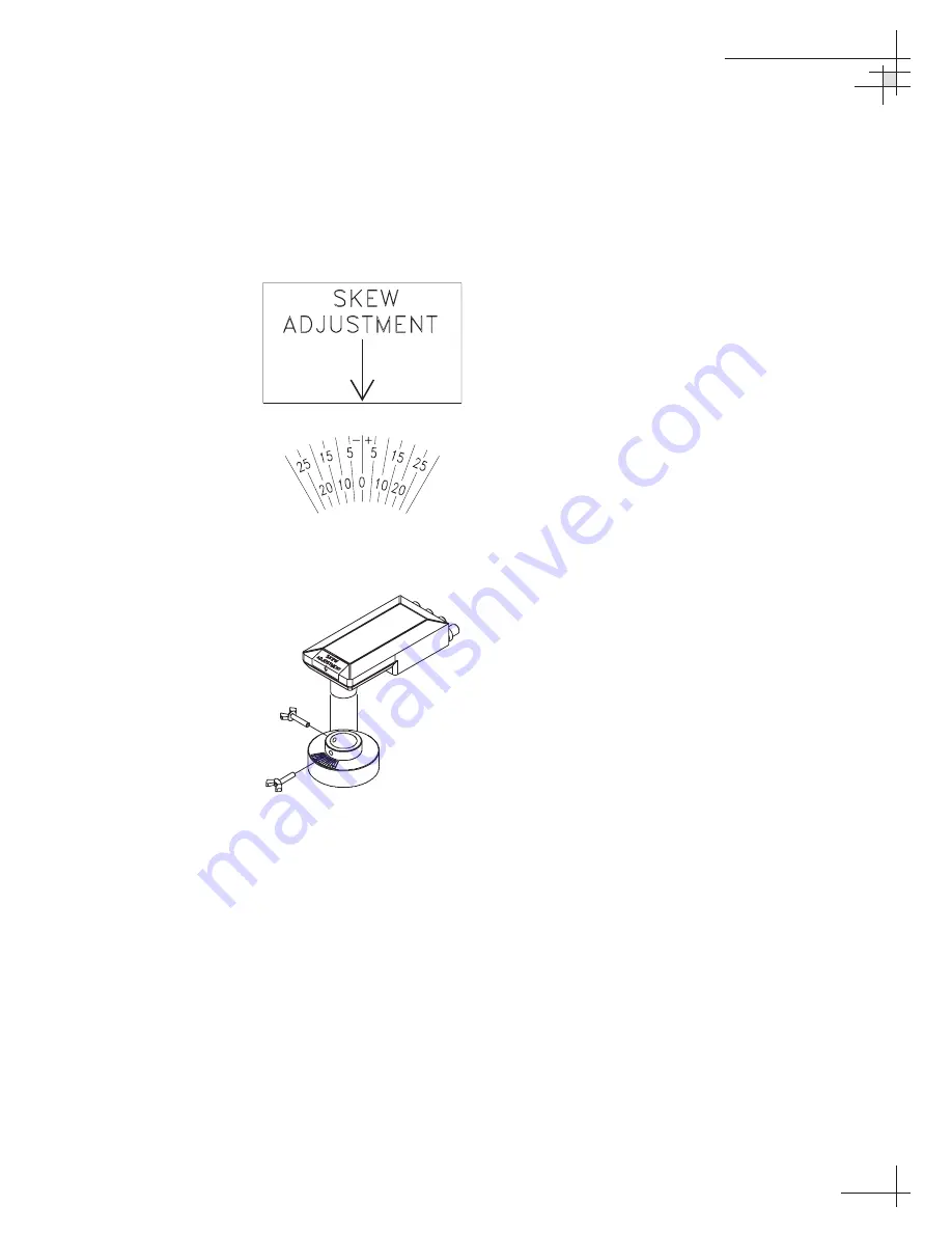
2. Observe the currently set skew value, as marked
by the stickers on the LNB and choke assembly
(see Figure 5-11).
3. Loosen the wing screws and remove the LNB from
the choke assembly (as shown in Figure 5-12).
4. Place the new LNB into the choke assembly.
Adjust the LNB’s position so that it has the same
skew value observed in Step 2.
5. Apply a small amount of thread-locking
compound (e.g., Loctite 425 or equivalent non-
permanent threadlocker) to the screw threads and
tighten the wing screws to secure the LNB in
position.
6. Reconnect the RF connectors.
Maintenance
54-0161
117
Figure 5-12
European LNB Removal
Figure 5-11
Skew Angle Labels


