4
ELECTRICAL CONNECTIONS
32
WATERFLUX 3070
www.krohne.com
06/2016 - 4004999701 - MA WATERFLUX 3070 - R01 en
4.6.2 IP68 housing (remote version)
Sensor cable:
refer to
Connection of the sensor cable
on page 30 for the available connection options
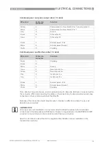
For connection of I/O ( modbus, pulse output signals) with or without additional power supply
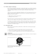
cable connection, several cable connection options are available. The cables have the following
color code leads.
Output pulse cable
Modbus cable
Figure 4-3: Different output cable, IP68 remote version
1
Color coded leads of sensor cable
2
Y - cable with additional power cable
3
I/O cable (pulse, modbus)
4
I/O connection
5
RVS sensor cable connection
Wire color
Contact on
connector
Function
Yellow
A
Status output 1 or threshold for P or T or pulse output C
White
G
Status output 2 or threshold for P or T
Blue
H
Ground
Brown
B
Pulse output A
Green
F
Pulse output B
Pink
C
External b
Grey
E
External battery -
Wire color
Contact on
connector
Function
Yellow
1
Down link wire B
←
Grey
1
Up link wire B
→
Pink
2
Up link wire A
→
Green
2
Down link wire A
←
White
3
Ground
Brown
-
-
Shield
Earth


