background image

 Kontron IP Network Server NSC2U

December 2009

Product Guide, rev. 1.4

93

Optional Component Installations—NSC2U Server

4.8.1

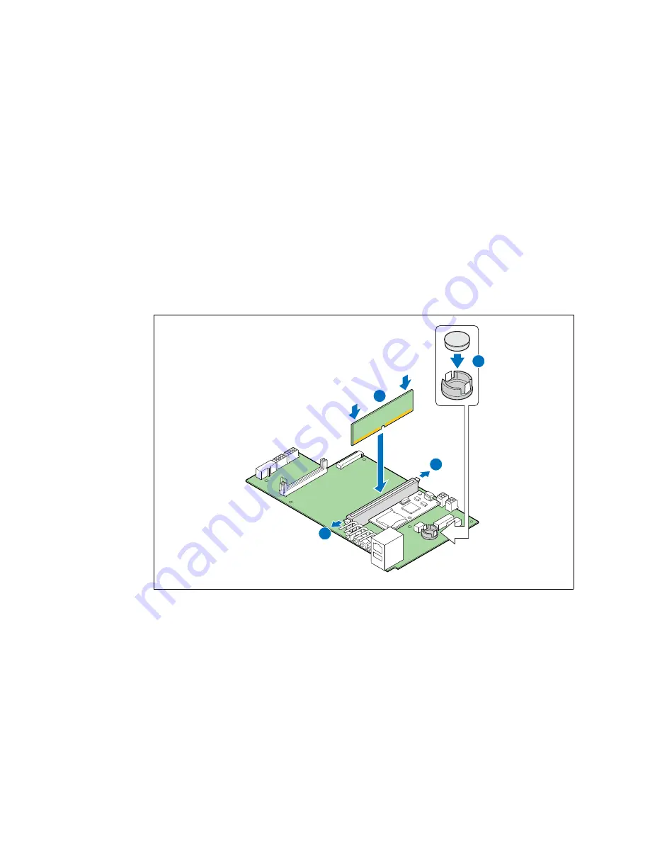
Installing the RAID Key and RAID DIMM 

1. Install the RAID activation key by inserting it into the socket. (

Figure 78

, “C”)

The wider rim is the top side of the key and faces up in the socket.

Make sure the metal clips on the socket snap securely over the edge of the RAID 

key top rim.

Caution:

Observe proper ESD and safety procedures when handling the RAID DIMM and the SFP 

board.

2. Open the latches on both ends of the RAID DIMM connector header. (

Figure 78

“A”)

3. Note the location of the alignment notch (“B”) and insert the DIMM.

Make sure the edge connector on the DIMM aligns properly with the connection 

header.

4. Using both hands, press down firmly and evenly on both sides of the DIMM until it 

snaps into place and both latches on the connector header close.

4.8.2

Installing the RAID Intelligent Battery Backup Unit (IBBU)

The RAID IBBU is installed on the side wall of the chassis by the SAS Front Panel 

(SFP)board. The connector, C8B3, is on the far right-most end of the SFP board. Before 

you install it, be sure to remove the front panel bezel.

The IBBU has an internal battery power cable that must be connected.

1. Open the IBBU case lid. If necessary, use a small flat-blade screwdriver to pry open 

the lid at the corners. (

Figure 79

, “A”)

2. If the battery power cable is not connected, connect it now. (“B”)

Figure 78.

Installing the RAID DIMM and RAID Key

TS0002

8

4

A

A

B

C

Summary of Contents for NSC2U

Page 1: ...Kontron IP Network Server NSC2U Product Guide December 2009 Rev 1 4...

Page 2: ...n purposes only and not guaranteed for legal purposes Information has been carefully checked and is believed to be accurate however no responsibility is assumed for inaccuracies Kontron and the Kontro...

Page 3: ...0 5 Fan Speed Control 23 2 10 6 Cooling Summary 23 2 11 Hardware Requirements 24 2 11 1 Processor 24 2 11 2 Memory 24 3 Server Component Installations and Upgrades 25 3 1 Before You Begin 25 3 1 1 Too...

Page 4: ...PCI Add in Card 51 4 2 1 Riser Card Options 52 4 2 2 Removing the PCI Riser Card Assembly 53 4 2 3 Removing an Add in Card from the Riser Card Assembly 53 4 2 4 Installing an Add in Card in the Riser...

Page 5: ...s 115 5 6 Replacing the Server Board 116 5 6 1 Removing the Server Board 117 5 6 2 Installing the Server Board Back into the Chassis 118 5 7 Replacing the Backup Battery on the Server Board 120 6 Serv...

Page 6: ...A Safety Information 137 A 1 Emissions Disclaimer 137 A 2 Intended Uses 137 A 2 1 If AC power supplies are installed 137 A 2 2 If DC power supplies are installed 138 A 2 3 Temperature and Ventilation...

Page 7: ...ons for Intel Z U130 Valid Solid State Drive May 2007 003 Updated Chapter 6 Server Utilities and reordered procedure steps rev 1 1 May 2007 002 Updated with review comments and new information rev 0 8...

Page 8: ...NSC2U Server Revision History Kontron IP Network Server NSC2U Product Guide rev 1 4 December 2009 8...

Page 9: ...mory DIMMs Use this chapter for step by step instructions and diagrams for installing or replacing components Chapter 4 provides instructions on adding optional ccomponents such as PCI add in cards I...

Page 10: ...six HDDs PCI X or PCIe add in cards Additional AC or DC power supply for redundancy and hot swapping Intel Remote Management Module RMM Advanced Edition and GCM module I O expansion module for dual G...

Page 11: ...Server Hardware peripheral boards add in cards and operating systems that have been tested with this product DIMMs that have been tested with this product The power budget for this product Software to...

Page 12: ...marizes the major features of the server system Figure 1 IP Network Server NSC2U TS000230 Table 1 IP Network Server NSC2U Features Feature Description Compact high density system Rack mount server wit...

Page 13: ...PCIe slots One full height full length 64 bit x 133 MHz PCI X slot Two low profile half length x4 PCI Express slots Six internal hot swappable SAS disk drives One optical drive optional Front panel S...

Page 14: ...dule with provision for an optional second module H SAS Front Panel SFP board can include optional SMART eUSB SSD which provides local memory storage C Provision for PCI X and PCI Express PCIe full he...

Page 15: ...eo connector C Ground studs used for DC input system J GbE NIC 2 connector D Power supply 2 slot filler panel shown K GbE NIC 1 connector E Power supply 1 L RJ45 serial port connector F GCM port conne...

Page 16: ...ver Front View Bezel Removed Item Description Item Description A Anti static connection point H Hard drive bay 0 B Optical drive optional or filler panel if no drive is installed I Hard drive bay 2 C...

Page 17: ...the main output power from the power supply is turned off or the power source is disrupted B System Status green amber Indicates system status as follows Steady green indicates system in standby or r...

Page 18: ...ans The SAS drives connect into the SFP board for power and signals The SFP board also provides fan power connectors and the user interface for the system s front panel 2 5 1 SFP Board Features The NS...

Page 19: ...that provides data caching for hardware RAID a connector for the Intelligent Battery Backup Unit IBBU that allows the contents of the DDR2 mini DIMM to be preserved if power falls below specifications...

Page 20: ...al slots on the T5000PAL server board One of the riser card slots is a PCI super slot that contains all the signals necessary to support both PCI X and PCI Express PCIe expansion slots The riser card...

Page 21: ...the Kontron IP Network Server NSC2U Technical Product Specification 2 8 2 Low profile PCIe Riser Card The low profile PCIe riser card plugs into the server board and supports the connection of low pr...

Page 22: ...Area One of the system s big fans provides cooling for domain 2 outlined in green in Figure 8 This fan facilitates the flow of air through the front bezel over the SFP through the fan and over the ser...

Page 23: ...sed on the ambient temperature monitored by the front panel sensor the fan speeds PWM duty cycle are set per Table 4 2 10 6 Cooling Summary The four fan cooling subsystem of the NSC2U Server is sized...

Page 24: ...ported processors see the Configuration Guide at http us kontron com products systems and servers and platforms communication rackmount servers ip network servers ip network server nsc2u html Click on...

Page 25: ...2 System References All references to left right front top and bottom assume that you are facing the front of the server as it would be positioned for normal operation 3 2 General Installation Procedu...

Page 26: ...of the chassis 2 Press down slightly on the chassis cover behind the peripheral area and slide the cover forward until it clicks into place 3 Install the shipping screw if tooled entry is required or...

Page 27: ...ct the 4xGbE cables if they are used 3 2 5 Removing the Processor Air Duct The air duct must be removed to access the processors memory DIMMs CPU fan assembly the SFP board or the inside of the front...

Page 28: ...ace the chassis cover if you have completed all work inside of the chassis 3 3 Hot Swappable Component Installation Procedures The following components are hot swappable and do not require powering do...

Page 29: ...Chassis 1 Remove the front bezel For instructions see Section 3 2 3 Removing the Front Bezel 2 Select the drive bay where you want to install the drive and remove the drive tray by pressing the green...

Page 30: ...ews that come with the drive tray Figure 14 A and B 3 With the drive tray locking lever fully open push the hard drive tray into the drive bay in the chassis until it stops Figure 15 A 4 Press the lev...

Page 31: ...unplug the power cord s from the system or wall outlet To maintain hot swap capability make sure that there is an active power supply module in both chassis slots before replacing hot swapping a powe...

Page 32: ...be used for proper safety grounding See C in Figure 3 for the location of the ground studs A crimping tool may be needed to secure the terminal lug to the grounding cable 3 4 Internal System Componen...

Page 33: ...mper block at J3H1 located just to the left of the SSI control panel header see Figure 18 is used to select which BIOS image the system will boot to Pin 1 on the jumper is identified with a Figure 17...

Page 34: ...ect Jumper Note This jumper affects the rear panel serial port only Various serial port concentrators may require either the DCD Data Carrier Detect or DSR Data Signal Ready signal on Pin 7 of the RJ4...

Page 35: ...DIMM memory channels are organized into two branches for support of RAID 1 mirroring The MCH can support up to 8 DIMMs for a maximum memory size of 32 Gbytes of physical memory in non mirrored mode a...

Page 36: ...and correction memory scrubbing retry on correctable errors memory built in self test DIMM sparing and memory mirroring See the Intel S5000 Series Chipsets Server Board Family Datasheet for more info...

Page 37: ...D1 3 A2 and B2 4 C2 and D2 DIMMs within a given pair must be identical with respect to size speed and organization However DIMM capacities can be different between different DIMM pairs For example a...

Page 38: ...e server board is capable of supporting a minimum of one installed DIMM However for system performance reasons Kontron recommends that at least two DIMMs be installed Figure 21 shows the recommended m...

Page 39: ...he minimum memory upgrade increment is two DIMMs per branch The DIMMs must cover the same slot position on both channels DIMM pairs must be identical with respect to size speed and organization DIMMs...

Page 40: ...emory configuration four additional DIMMs must be added to the system All four DIMMs in the second set must be identical to the first with the exception of speed The MCH will adjust to the lowest spee...

Page 41: ...dentical in organization size and speed DIMM B1 and DIMM B2 need not be identical in organization size and speed DIMM C1 and DIMM C2 need not be identical in organization size and speed DIMM D1 and DI...

Page 42: ...l it snaps into place and the levers close C and D IMPORTANT Visually check that each latch is fully closed and correctly engaged with notch on the DIMM edge E 7 Replace the air duct and chassis cover...

Page 43: ...ructions that came with the processor Caution The processor must be appropriate You could damage the server board if you install a processor that is inappropriate for your server Go to http us kontron...

Page 44: ...ink with a 2 Phillips screwdriver Section 26 A 2 Twist the heat sink slightly to break the seal between the heat sink and the processor B 3 Lift the heat sink from the processor If it does not pull up...

Page 45: ...Figure 27 5 Pull the lever and open the load plate all the way A and B in Figure 28 6 Remove the processor 3 4 5 3 Installing a New Processor Note Follow the ESD precautions covered in Section 3 4 5...

Page 46: ...lace the processor onto the socket surface Do not drop the processor into the socket 2 Orient the processor with the socket so that the processor cutouts match the socket notches See Figure 30 A 3 Gen...

Page 47: ...ining up the four captive screws with the four posts surrounding the processor Align the heat sink fins to the front and back of the chassis for correct airflow front to back Use caution and make sure...

Page 48: ...accessible for disconnection then you are responsible for installing a power disconnect for the entire rack unit This main disconnect must be readily accessible and it must be labeled as controlling...

Page 49: ...include ventilation sufficient to exhaust a maximum of 1200 BTU per hour for a fully loaded server system using the IP Network Server NSC2U It is important to note that this measurement is the maximu...

Page 50: ...ction by wearing an antistatic wrist strap attached to chassis ground any unpainted metal surface on your server when handling parts 4 1 1 Tools and Supplies Needed 1 and 2 Phillips cross point screwd...

Page 51: ...iser cards A combination PCI X PCI Express PCIe riser card for full height add in cards A PCIe riser card with two slots for low profile add in cards The riser card assembly is attached to the T5000PA...

Page 52: ...full height riser card the NSC2U Server supports PCI X PCIe x1 PCIe x4 and PCIe x8 Table 11 summarizes the possible board installation configurations The low profile riser slot J5B1 uses a 98 pin con...

Page 53: ...in Card from the Riser Card Assembly Caution When handling an add in card observe the normal safety and ESD precautions See Appendix A Safety Information for more information 1 Turn the riser card ass...

Page 54: ...anel 2 For a full height card remove the front retention clip by loosening the blue captive thumbscrew and rotating the clip outward Figure 36 D and C Disengage the three plastic tabs from the metal s...

Page 55: ...ng the server in a rack see Section 3 5 Installing the Server into a Rack on page 48 4 3 Installing an I O Expansion Module There are two types of optional I O expansion modules available for the IP N...

Page 56: ...nector B and the standoffs 6 If this is the last task you are performing replace the riser card assembly the processor air duct and the top cover of the chassis Reconnect all the external devices and...

Page 57: ...e server board using the connector D 4 If this is the last task you are performing replace the riser card assembly the processor air duct and the top cover of the chassis Reconnect all the external de...

Page 58: ...ard assembly as described in Section 4 2 Installing or Replacing a PCI Add in Card replacing one of the front panel filler panels with a 4xGbE escutcheon and routing the LAN cables to the front panel...

Page 59: ...iser card assembly bracket using the rear retention screw D 4 5 2 Configuring the RJ45 GbE LAN Card Caution When handling the LAN card observe the normal safety and ESD precautions See Appendix A Safe...

Page 60: ...e 43 A 6 Leave the LED ribbon cable out of the retention clip Note Do not fully re install the riser card assembly in the chassis yet The connection to the front panel must be set up first Put the ass...

Page 61: ...mbly on page 102 2 Disconnect the PCI fan assembly power cables and remove the fan assembly from the chassis For instructions see Section 5 2 3 Removing the PCI Fan Assembly on page 102 3 Remove the c...

Page 62: ...e the GbE cables and LED ribbon cable to the front of the chassis 7 Route the cables along the SAS backplane and along the right side of the SAS drive bayassembly 8 Secure the GbE cables with the cabl...

Page 63: ...front panel LAN access the filler panel must be removed and the GbE escutcheon installed Then the 4xGbE connector assembly can be attached to the escutcheon Once these steps are done the components th...

Page 64: ...ting the two tabs on the top into the front panel opening and then fastening the escutcheon with the two screws removed from the filler panel with a Phillips screwdriver Figure 48 A and B 3 Insert the...

Page 65: ...flex cable over the PCI fan assembly and the support bracket and connect it to the SAS backplane board 7 Install the PCI riser card assembly back into the chassis For instructions seeSection 4 2 5 Rep...

Page 66: ...t Panel Access The IP Network Server NSC2U supports the Intel PRO 1000 PF Quad Port Bypass Adapter LAN card installed in the full height riser card slots with connections routed to the front panel 4 6...

Page 67: ...ver NSC2U December 2009 Product Guide rev 1 4 67 Optional Component Installations NSC2U Server 2 Remove the power supply support bracket as shown in Figure 51 Figure 51 Removing the power supply suppo...

Page 68: ...onal Component Installations Kontron IP Network Server NSC2U Product Guide rev 1 4 December 2009 68 3 Remove the blue flex cable support as shown in Figure 52 Figure 52 Removing the Blue Flex Cable Su...

Page 69: ...December 2009 Product Guide rev 1 4 69 Optional Component Installations NSC2U Server 4 Disconnect the flex cable letter A in Figure 53 and move it away from the PCI fan assembly B Figure 53 Disconnect...

Page 70: ...C2U Product Guide rev 1 4 December 2009 70 5 Unplug and remove the PCI fan assembly Disconnect the power cables cables letter A in Figure 54 Hold down the PCI card carrier assembly B and lift out the...

Page 71: ...cember 2009 Product Guide rev 1 4 71 Optional Component Installations NSC2U Server 6 Press on the tabs letter A in Figure 55 and lift out the PCI card carrier assembly B Figure 55 Removing the PCI Car...

Page 72: ...roduct Guide rev 1 4 December 2009 72 7 Open the retaining clip letter A in Figure 56 and lift the end of the bridge board out of the connector B Install the fiber bundle retention clip around the bri...

Page 73: ...r 2009 Product Guide rev 1 4 73 Optional Component Installations NSC2U Server 8 Re install the bridge board back into the connector letter A in Figure 57 and close the retention clip B Figure 57 Re in...

Page 74: ...the Fiber LAN Card and install it into the chassis 9 Starting with Fiber pair A remove the wires from the white cable clips letter A in Figure 58 and trace the wires back to the pulse transformer B R...

Page 75: ...Product Guide rev 1 4 75 Optional Component Installations NSC2U Server 10 Install the cable management sheath around the four Fiber pairs as shown in Figure 59 Figure 59 Installing the Cable Manageme...

Page 76: ...ll be using for the Fiber LAN card A in Figure 60 Loosen the blue thumbscrew on the retention clip and rotate the clip outward B Insert the LAN card into the selected full height PCI Express riser car...

Page 77: ...t Installations NSC2U Server 12 Plug the ribbon cable into the LAN card A in Figure 61 Route the cable through the clip in the card retention mechanism B Route the fiber cables over the correct edge C...

Page 78: ...13 Grasp the PCI riser card assembly using the two flexible blue handles and carefully re insert the assembly into the chassis A in Figure 62 Note the pins on each side of the rear panel opening wher...

Page 79: ...rev 1 4 79 Optional Component Installations NSC2U Server 14 Route the fiber cable bundle alongside the bridge board Secure the two using the fiber bundle retention clip as shown in Figure 63 Figure 6...

Page 80: ...Escutcheon and Connect the Fiber Cables 15 Remove the screws holding the blank front panel cover letter A in Figure 64 Slide the blank cover off B 16 Install the interposer LED board onto the fiber e...

Page 81: ...Product Guide rev 1 4 81 Optional Component Installations NSC2U Server 17 Install the fiber escutcheon into the front of the chassis A in Figure 66 Secure the escutcheon using two screws B Figure 66...

Page 82: ...rk Server NSC2U Product Guide rev 1 4 December 2009 82 18 Slide the bluefiber connectors into the escutheon as shown in Figure 67 Slide the connectors in until you hear the retaining clips snap Figure...

Page 83: ...rev 1 4 83 Optional Component Installations NSC2U Server 19 Route the ribbon cable through the cable retention mechanism A in Figure 68 Plug the ribbon cable into the interposer board B Figure 68 Rou...

Page 84: ...2U Product Guide rev 1 4 December 2009 84 20 Remove the white protective caps from the ends of the fiber cable pairs A in Figure 69 Slide the cables into the blue fiber connectors on the escutcheon B...

Page 85: ...9 Product Guide rev 1 4 85 Optional Component Installations NSC2U Server 4 6 4 Re assemble the System 21 Re install the PCI fan assembly A in Figure 70 and plug in the power connectors B Figure 70 Re...

Page 86: ...Component Installations Kontron IP Network Server NSC2U Product Guide rev 1 4 December 2009 86 22 Move the flex cable back into position A in Figure 71 and reconnect it B Figure 71 Reconnecting the Fl...

Page 87: ...ver NSC2U December 2009 Product Guide rev 1 4 87 Optional Component Installations NSC2U Server 23 Re install the blue flex cable support as shown in Figure 72 Figure 72 Re installing the Blue Flex Cab...

Page 88: ...nent Installations Kontron IP Network Server NSC2U Product Guide rev 1 4 December 2009 88 24 Re install the power supply support bracket as shown in Figure 73 Figure 73 Re Installing the Power Supply...

Page 89: ...IP Network Server NSC2U December 2009 Product Guide rev 1 4 89 Optional Component Installations NSC2U Server 25 Re install the top cover as shown in Figure 74 Figure 74 Re installing the Top Cover A T...

Page 90: ...des a means for routing and managing LAN cables connected to the front of the system chassis The bracket is symmetrical and can be mounted on either side of the bezel To attach the bracket on the righ...

Page 91: ...panel LED light pipes Before you install an SSD you must remove the chassis top cover the front bezel and the processor air duct 1 Remove the chassis top cover and the processor air duct For instructi...

Page 92: ...tion 3 5 Installing the Server into a Rack on page 48 4 8 Installing Hardware RAID 5 Components The RAID5 Kit includes the following three components for hardware RAID support Hardware RAID activation...

Page 93: ...IMM Make sure the edge connector on the DIMM aligns properly with the connection header 4 Using both hands press down firmly and evenly on both sides of the DIMM until it snaps into place and both lat...

Page 94: ...panel to lock it into place The plastic tab on the IBBU case goes into the slot in the chassis See the red arrow in Figure 81 B 8 Connect the cable from the IBBU to the connector on the SFP board C 9...

Page 95: ...Installation Procedures on page 25 4 9 1 Removing the Optical Device Filler Panel from the Chassis 1 Remove the chassis top cover 2 Remove the front panel bezel from the chassis to access the optical...

Page 96: ...panel Save the guide and the two screws for use on the new optical device 4 9 2 Installing a New Optical Device 1 Align the pins in the retention mechanism to the corresponding holes in the side of t...

Page 97: ...drive in the properly aligned position A 3 If this is the last task you are performing replace the processor air duct and the top cover of the chassis Reconnect all the external devices and plug in t...

Page 98: ...attached to chassis ground any unpainted metal surface on your server when handling parts 5 1 1 Tools and Supplies Needed 1 and 2 Phillips cross point screwdrivers or interchangeable tip screwdriver w...

Page 99: ...st first take the server out of service turn off all peripheral devices connected to the system turn off the system by pressing the power button and unplug the power cord s from the system or wall out...

Page 100: ...Fans 1 Remove the chassis top cover and the processor air duct that covers the fans For instructions see Section 3 2 1 and Section 3 2 5 2 Unplug the CPU fan power cables from the front panel board F...

Page 101: ...within the notch in the bracket B 3 Make certain that the grommet heads on the other side of the fans rest near or against the SAS Front Panel Board C 4 Plug the fan power cables back into the SAS Fro...

Page 102: ...Fan Assembly Before the PCI fan assembly can be removed from the chassis the chassis cover must be removed and the flex cable that runs across the fan bracket must be disconnected 1 Remove the flex ca...

Page 103: ...mber 2009 Product Guide rev 1 4 103 2 Disconnect the flex cable from the SAS backplane board and lift the cable off of the PCI fan assembly Figure 89 A and B Figure 89 Removing the Flex Cable from ove...

Page 104: ...rev 1 4 December 2009 104 3 Disconnect the PCI fan assembly power cables from the SAS front panel SFP board Figure 90 A 4 Hold down the PCI cardcage assembly B 5 Lift the fan assembly out of the chas...

Page 105: ...fans from the fan shroud 2 Align the new fans into the fan shroud with the airflow arrows pointing toward the back of the chassis Figure 91 A 3 Fasten each fan into the shroud using four grommets A No...

Page 106: ...cable back over the PCI fan assembly Figure 93 A 4 Reconnect the flex cable to the SAS backplane board B 5 Re install the flex cable support bracket 6 If this is the last task you are performing repl...

Page 107: ...GbE LAN card cables connected to the front panel Add in Card Riser Assembly PCI fan assembly CPU fan assembly and air duct Caution Before replacing any of the boards on the NSC2U Server you must first...

Page 108: ...the CPU Fans on page 100 5 Disconnect all of the cables connected to the SFP board SAS backplane power cable All four fan power cables Two power input cables from the power distribution board Flex ca...

Page 109: ...ght pipe assembly so that you will be able to correctly position it or a replacement on the new SFP board during the re installation process The light pipes extend outward from the SFP board to the fr...

Page 110: ...page 107 8 Re connect the flex cable 9 Re install the CPU fan assembly For instructions see Section 5 2 2 Replacing the CPU Fans on page 101 10 Re connect all the power cables and the bridge board 11...

Page 111: ...nd unplug the power cord s from the system or wall outlet 5 4 1 Removing the Drive Bay Assembly 1 Disconnect the following cables that are attached to the SAS backplane board at the rear of the drive...

Page 112: ...rews that fasten the backplane board to the drive bay assembly Figure 98 A 3 Pull the backplane board off of the rear of the drive bay assembly 5 4 3 Installing a New SAS Backplane Board To install a...

Page 113: ...used can be installed into the drive bay assembly either before or after the assembly is installed in the chassis 1 Insert the drive bay assembly into the chassis Figure 100 A 2 Secure the drive bay...

Page 114: ...hole assembly that must be removed and replaced not just the board Caution Before replacing any of the boards in the NSC2U Server you must first take the server out of service turn off all peripheral...

Page 115: ...e the PCI fan assembly For instructions see Section 5 2 3 Removing the PCI Fan Assembly on page 102 7 Remove the CPU fan assembly For instructions see Section 5 2 1 Removing the CPU Fans on page 100 8...

Page 116: ...r information about mounting the server in a rack see Section 3 5 Installing the Server into a Rack on page 48 5 6 Replacing the Server Board The IP Network Server NSC2U uses the Intel Server Board T5...

Page 117: ...bly on page 53 4 Remove the CPU fan assembly For instructions see Section 5 2 1 Removing the CPU Fans on page 100 5 Remove the drive bay assembly For instructions see Figure 97 Removing the Drive Bay...

Page 118: ...inched under the board Insert the rear edge of the board first and line up the I O ports at the rear of the system 2 When placing the board into the chassis make certain that the board does not catch...

Page 119: ...a New Processor on page 45 b Install all DIMMs For instructions see Section 3 4 3 Installing DIMMs on page 41 c Install any I O expansion modules or remote management modules For instructions see Sect...

Page 120: ...t take the server out of service turn off all peripheral devices connected to the system turn off the system by pressing the power button and unplug the power cord from the system or wall outlet WARNI...

Page 121: ...he tab in the plastic retainer Gently push down on the screwdriver to lift the battery 7 Remove the battery from its socket 8 Dispose of the battery according to local ordinance 9 Remove the new lithi...

Page 122: ...you will see the prompt Press F2 to enter SETUP In a third condition when CMOS NVRAM has been corrupted you will see other prompts but not the F2 prompt Warning CMOS checksum invalid Warning CMOS time...

Page 123: ...oards the plus key has a different scan code than the plus key on the other keyboard but it has the same effect Enter Execute Command The Enter key is used to activate submenus when the selected featu...

Page 124: ...rding jumper settings specific fixes or other information to complete the upgrade 6 2 2 Updating the BIOS Follow the instructions in the readme file that came with the BIOS upgrade When the update com...

Page 125: ...unlikely event that the BMC firmware update process fails because the BMC is not in the proper update state the server board provides a BMC Force Update jumper that can force the BMC into the proper u...

Page 126: ...epth troubleshooting first attempt to reset your system using one of the methods below 7 2 Problems Following Initial System Installation Problems that occur at initial system startup are usually caus...

Page 127: ...upport for links to the tested component lists 7 3 Hardware Diagnostic Testing This section provides a more detailed approach to identifying a hardware problem and locating its source Caution Turn off...

Page 128: ...e system boots If successful re insert the cards one at a time with a reboot between each addition Make sure the memory DIMMs comply with the system requirements Make sure the memory DIMMs have been p...

Page 129: ...sped up in response to a fan that has failed Are the fan power connectors properly connected to the SFP board Is the cable from the front panel board connected to the both the front panel board and to...

Page 130: ...r button on the front of the system 2 Unplug the power cord from the server 7 4 10 Problems with Newly Installed Application Software Problems that occur when you run new application software are usua...

Page 131: ...e Go to http us kontron com support for a link to the list tested drives Make sure you have not exceeded the power budget for the server Go to http us kontron com support for a link to software to che...

Page 132: ...drive is not an ATAPI Advanced Technology Attachment Packet Interface device Run Setup to make sure device is selected correctly A Drive Error No response from diskette drive CMOS Battery Low The bat...

Page 133: ...nd passwords have been cleared The system should be powered down and the jumper removed CTRL_N Pressed CMOS is ignored and NVRAM is cleared User must enter Setup Table 15 BIOS Error Messages Sheet 2 o...

Page 134: ...uide rev 1 4 December 2009 134 1 5 4 2 DC power unexpectedly lost 1 5 4 3 Chipset control failure 1 5 4 4 Power control failure Table 17 Error Beep Codes Provided by a Remote Management Module Sheet 2...

Page 135: ...ts Within the warranty period the repair of products is free of charge as long as warranty conditions are observed The warranty does not apply to defects resulting from improper or inadequate maintena...

Page 136: ...NSC2U Server 8 Kontron IP Network Server NSC2U Product Guide rev 1 4 December 2009 136...

Page 137: ...ces Telecommunication Centers offices schools computer rooms and similar commercial type locations The suitability of this product for other product categories and environments medical industrial tele...

Page 138: ...A 2 2 If DC power supplies are installed Connection with a DC Direct Current source should only be performed by trained service personnel The server with DC input is to be installed in a Restricted A...

Page 139: ...uct Refer servicing only to qualified personnel Do not attempt to modify or use the supplied AC power cord if it is not the exact type required A product with more than one power supply will have a se...

Page 140: ...the system A microprocessor and heat sink may be hot if the system has been running Also there may be sharp pins and edges on some board and chassis parts Contact should be made with care Consider we...

Page 141: ...ein geerdetes Antistatik Gelenkband um elektrostatische Ladungen ESD ber blanke Metallstellen bei der Handhabung der Komponenten zu vermeiden 6 Schalten Sie das System niemals ohne ordnungsgem montier...

Page 142: ...len ausgesetzt sein einschlie lich direkter Sonneneinstrahlung keinen Ersch tterungen ausgesetzt sein keine starken von elektrischen Ger ten erzeugten elektromagnetischen Felder aufweisen in Regionen...

Page 143: ...s ou de pi ces d mont es dans le syst me 2 Assurez vous que les c bles les cartes d extension et les autres composants sont bien install s 3 Revissez solidement les panneaux du bo tier avec les vis re...

Page 144: ...s cables de alimentaci n CA del sistema o de las tomas de corriente alterna 4 Identifique y desconecte todos los cables enchufados a los conectores E S o a los puertos situados en la parte posterior d...

Page 145: ...para acceder a los cables de alimentaci n ya que stos hacen de medio principal de desconexi n del sistema Rivolgersi ad un tecnico specializzato per la riparazione dei componenti dell alimentazione di...

Page 146: ...tutti i cavi esterni e le prolunghe AC del sistema Se il sistema stato a lungo in funzione il microprocessore e il dissipatore di calore potrebbero essere surriscaldati Fare attenzione alla presenza...

Page 147: ...I CNS 13436 Taiwan B 1 2 Product EMC Compliance Class A Compliance The IP network server has been has been tested and verified to comply with the following electromagnetic compatibility EMC regulation...

Page 148: ...instructions may cause harmful interference to radio communications However there is no guarantee that interference will not occur in a particular installation If this equipment does cause harmful int...

Page 149: ...003 of the Canadian Department of Communications B 2 3 Europe CE Declaration of Conformity This product has been tested in accordance to and complies with the Low Voltage Directive 73 23 EEC and EMC...

Page 150: ...ards must have a printed wiring board flammability rating of minimum UL94V 1 Add in boards containing external power connectors and or lithium batteries must be UL recognized or UL listed Any add in b...

Page 151: ...iaries are available for technical support We are committed to making our product easy to use and will help you use our products in your systems Please consult our Web site at http us kontron com supp...

Page 152: ...NSC2U Server C Kontron IP Network Server NSC2U Product Guide rev 1 4 December 2009 152...

Reviews: