Kontron KISS4U User Manual Download Page 20

 
page 20                                                                                            KISS4U  User’s  Guide


1

2

5

3

13

6

10

12

14

8

9

11

9

7

4

15


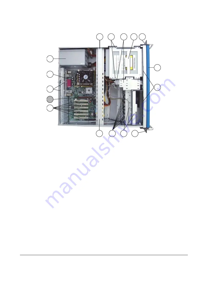
Figure 2: KISS-Platform, opened rackmount version with motherboard 


Legend for figures 2 and 3: 

1.  Power supply unit 
2. Motherboard (example) 
3.  Exhaust openings on the rear 

side 

4.  Free AGP-slot (available only in 

KR4101-886M) 

5.  Free expansion slots (depends 

on system configuration) 

6. Card holder 
7. Card guides 
8.  Fan slide-in module with captive 

knurled screw 

9.  19” rack mountable bracket with 

handle (not available for tower 
and desktop version) 

10. Guide openings for the cover 
11. Front access door 
12. Drive cage for 3x 5.25“ drive bay 

and 1x 3.5“ internal drive bay 

13. Drive bracket for 2x 3.5“ drive 

bay 

14. Drive locking screws 
15. Fastening screw for the card 

holder 

16. External interfaces of the 

motherboard 

17. Grounding  stud 
18. Expansion  card  slots 


Summary of Contents for KISS4U

Page 1: ...KISS4U User s Guide PN 930 0049 00 January 2007 Kontron America...

Page 2: ...rotected by copyrights or patents and does not convey any license under the patent rights of Kontron nor the rights of others Kontron is a registered trademark of Kontron All trademarks registered tra...

Page 3: ...Optional Parts 17 Type Label and Product Identification 17 Product Description 17 Versions of the KISS Platform 18 Front Side 24 Operating Elements 26 Interfaces on the Front Side 27 Rear Panel 28 In...

Page 4: ...Port 45 Operating System and Hardware Component Drivers 46 Chapter 3 Maintenance and Prevention 47 Replacing the System s Fans 47 Cleaning the Filter Mat 50 Replacing the Lithium Battery 52 Appendix...

Page 5: ...7P7I 34 Figure 13 Backplane KR 4201 Series with BP10 12P 34 Figure 14 KISS Drive cage with drive locking screws 38 Figure 15 Loosen the captive knurled screws 39 Figure 16 Removing the device cover 3...

Page 6: ...page 6 KISS4U User s Guide This page intentionally left blank...

Page 7: ...ating a computer Only qualified experienced authorized electronics service personnel should access the interior of a computer The power supplies produce high voltages and energy hazards which can caus...

Page 8: ...ropriate To help avoid possible damage to system boards wait five seconds after turning off the computer before removing a component removing a system board or disconnecting a peripheral device from t...

Page 9: ...t s antistatic packing material until you are ready to install the component in a computer Just before unwrapping the antistatic packaging be sure you are at an ESD workstation or grounded This will d...

Page 10: ...page 10 KISS4U User s Guide This page intentionally left blank...

Page 11: ...on replacing fans filters and batteries Appendix A Slide Rails Optional provides instructions on how to install the optionally available slide rails for use in a 19 industrial cabinet Appendix B Troub...

Page 12: ...A note is used to make helpful information stand out Important An important note indicates information that is important for you to know CAUTION A CAUTION indicates potential damage to hardware and t...

Page 13: ...he interference at their own expense You are cautioned that changes or modifications not expressly approved by Kontron could void your authority to operate the equipment This device complies with Part...

Page 14: ...in an as new and resalable condition are not eligible for a credit return and will be returned to the customer Limited Warranty Effective April 1 1998 all products carry a 2 year limited warranty Wit...

Page 15: ...repairs and building replacement products If Kontron repairs or replaces a product its warranty term is not extended Kontron will normally return your replacement or repaired items via ground Overnigh...

Page 16: ...rial for possible future shipment 2 Remove all items from the box If any items listed on the purchase order are missing notify Kontron customer service immediately 3 Inspect the product for damage If...

Page 17: ...with 886LCD GV Motherboard KR 4101 886M KISS with 886LCD M ATX Motherboard KR 4101 MB945G KISS with MBATX 945G VGA Motherboard KR 4201 PCI951 KISS with PCI 951 SBC board Single Board Computer Product...

Page 18: ...h opened access door The system is equipped with five front accessible drive bays two 3 5 and three 5 25 bays The operating controls of the KISS Platform are located behind the front access door and i...

Page 19: ...ccess door The outside accessible filter mat is changeable while the KISS Platform is powered up The type label is attached to the right side of the unit Figure 1 KISS Platform CAUTION When switching...

Page 20: ...ots depends on system configuration 6 Card holder 7 Card guides 8 Fan slide in module with captive knurled screw 9 19 rack mountable bracket with handle not available for tower and desktop version 10...

Page 21: ...ake sure that the air intake and exhaust openings are not obstructed by objects CAUTION For rack and desktop versions only Before putting the system into operation for the first time before mounting i...

Page 22: ...Exhaust openings on the rear side 5 Single Board Computer example 6 Card holder 7 Card guides 8 Fan slide in module with captive knurled screw 9 Guide openings for the cover 10 Front access door 11 Dr...

Page 23: ...ystem make sure that the air intake and exhaust openings are not obstructed by objects CAUTION For rack and desktop versions only Before putting the system into operation for the first time before mou...

Page 24: ...unit by removing the two 19 rack mountable bracket with handle one off on each side Figure 7 19 rack mountable bracket with fastening screws 1 Chassis of the KISS Platform 2 19 rack mountable bracket...

Page 25: ...ess door 2 Bracket with knurled screw for the air filter mat 3 LED indicators 4 Slot for the locking mechanism 5 2x 3 5 drive bay shown with one FDD installed 6 3x 5 25 external accessible drive bay s...

Page 26: ...still a standby voltage of 5V on the SBC board motherboard The system is not completely disconnected from the main power source by turning off the with the ATX power button The unit is completely dis...

Page 27: ...power cord to an appropriate power source The power switch of the PSU located on the rear side of the unit must be set to On for those systems equipped with a PSU with PSU switch HDD Activity LED oran...

Page 28: ...sible Slim Line or Internal 3 5 Drive Bay Option The KISS desktop and rackmount versions can be optionally equipped with 1x internal not visible from the outside 3 5 drive bracket in horizontal positi...

Page 29: ...Captive knurled screws to secure the cover 8 Device cover 9 Air exhaust openings 10 Interfaces of the SBC board or of the motherboards depending on the system configuration 11 Additional serial inter...

Page 30: ...ces COM1 COM2 These connections are available as 9 pin D SUB plugs and allow you to connect serial peripherals These additional interfaces are configured as RS232 Refer to the information and technica...

Page 31: ...friendly exchangeable fan slide in module hot swappable The fan slide in module is installed in the fan case located at the front side of the system The system fans are temperature controlled via the...

Page 32: ...can be used to attach slide rails not included in the scope of delivery to the KISS Platform for system installation into a 19 industrial cabinet Refer to the Slide Rails Option chapter 2 1 Figure 11...

Page 33: ...945G VGA Motherboard KR 4201 PCI951 PCI 951 Single Board Computer Refer to the information and technical data in the supplied user manual of the motherboard or SBC board Important Depending on the or...

Page 34: ...P10 7P7I 1 2x 32 bit PICMG 1 0 CPU slot 2 5x 16 bit ISA slot 3 7x 32 bit PCI slot Figure 13 Backplane KR 4201 Series with BP10 12P 1 2x 32 bit PICMG 1 0 CPU slot 2 11x 32 bit PCI slot 3 1x 16 bit ISA...

Page 35: ...BC board refer to SBC User s Manual Additional interfaces 2x USB 1 1 2 0 1x COM1 configured as RS232 1x COM2 configured as RS232 1x LPT1 For systems with motherboard Interfaces of the motherboard refe...

Page 36: ...2x system fans temperature controlled 1x power supply fan temperature controlled 1x CPU fan Operating temperature relative humidity 0 50 C 5 90 not condensing 32 122 F 5 90 not condensing Storage tran...

Page 37: ...off the power supply switch and disconnect the power cord from its source before removing the chassis cover Simply turning the system power off at the system power on off switch does not remove power...

Page 38: ...and that the system cover is installed and secured 2 Turn the system upside down 3 Remove the protect foil from the delivered self adhesive rubber feet 4 Attach the self adhesive rubber feet to the b...

Page 39: ...y boards or replacing the fan slide in module Installing Removing the Expansion Cards To install or remove an expansion card perform the following steps 1 Turn off all power sources Disconnect the pow...

Page 40: ...ht 2 to pull it out from the two laterally located bolts Lift the card hold down bracket away 3 Retain the card hold down bracket and the screw for later use Figure 18 Removing the fastening screw the...

Page 41: ...the device 6 Reinstall the card holder and secure it using the retaining screw see fig 18 7 The PCP holder has to be installed into the appropriate hole of the card hold down bracket by means of the...

Page 42: ...a 19 industrial cabinet with mounting rails Check the load capacity of the mounting rails the unit may weigh up to 20 kg approx 44 lbs Ensure there is sufficient air circulation around the device when...

Page 43: ...igure 21 AC Power connection Motherboard AC power plug Figure 22 AC Power connection Backplane CAUTION The voltage of the power source must agree with the voltage value on the type label 1 Connect the...

Page 44: ...er cord suitable for the power supply in your country Do not remove or alter the grounding prong on the power cord In situations where a two slot receptacle is present have it replaced with a properly...

Page 45: ...tect 2 RXD Receive Data 3 TXD Transmit Data 4 DTR Data Terminal Ready 5 GND Signal Ground 6 DSR Data Set Ready 7 RTS Request to Send 8 CTS Clear to Send 9 RI Ring Indicator Parallel Port Pin Signal na...

Page 46: ...rresponding to the ordered configuration optional hardware components Your computer is fully functional when you switch it on for the first time If you have ordered your system without a pre installed...

Page 47: ...Replacing the System s Fans section Defective components should only be replaced with Kontron original spare parts the part number of the fan slide in module 0 0084 3604 Note The fan slide in module...

Page 48: ...age 48 KISS4U User s Guide Figure 23 KISS Platform with fan slide in module nach oben heraus 2 5 3 Figure 24 Side view of the fan slide in module 5 3 6 Figure 25 Bottom view of the fan slide in module...

Page 49: ...dule 7 Socket in the fan case for fan control 8 Centering angle 9 Fan case Figure 26 Fan case of the KISS Platform without fan slide in module 3 Replace the fan slide in module with a new functional m...

Page 50: ...he air filter mat to the chassis 3 Pull out the filter mat holder into the marked direction 4 Remove the dirty air filter mat 5 To clean the filter mat Rinse in water up to approx 40 C you may add mil...

Page 51: ...pare parts the part number of the filter mat 0 0084 2953 3 1 2 Figure 28 Location for filter mat holder 5 4 6 7 4 6 Figure 29 Filter mat holder with and without filter mat Legend for figures 28 and 29...

Page 52: ...ector spring 4 Place the new battery into the socket 5 Make sure that you insert the battery the right way around The plus pole must be on the top 6 The lithium battery must be replaced with an identi...

Page 53: ...gure 30 Attaching the inner side of the slide rail Figure 31 Kiss Plattform with slide rail Legend for figures 30 and 31 1 Side view of the KISS Platform 2 4x M4x6 rounded head screws per each side of...

Page 54: ...set consists of the following elements One pair of slide rails One pair of short front brackets with screws and washers One pair of long rear brackets with screws and washers 2 x bar nut kits 8 x M4x...

Page 55: ...quare to the industrial cabinet 2 Using mounting kits and brackets mount the brackets to the outer part of the slide rails see fig 31 pos 4 Screw the back brackets on loosely 3 Install the slide rails...

Page 56: ...page 56 KISS4U User s Guide This page intentionally left blank...

Page 57: ...th high voltage which could injure you Avoid shorting the circuits as this can damage the computer CAUTION The following procedures involve working with a device that is sensitive to static electricit...

Page 58: ...ables to fans and disk drive cables Occasionally Flash BIOS can be corrupted by hardware or software Check the Kontron Web site for the latest version of BIOS and follow the steps for reflashing When...

Page 59: ...tem is not booting just beeping Memory is not seated correctly or is faulty 1 beep 2 beeps or 3 beeps Re seat the memory first If that does not fix the problem replace the memory with known good chips...

Page 60: ...page 60 KISS4U User s Guide This page intentionally left blank...

Reviews: