background image

Field Service Ver. 1.0 May 2006

5. Firmware upgrade

31

magicolor 7450

Maintenance

6.

Wait until all of the data is sent. 
While the data is being sent, [FIRMWARE UPDATE] and [PROCESSING] are alter-
nately displayed on the screen.

NOTE
• NEVER turn the printer Power Switch OFF and ON while data is being sent.

7.

After the data has finished being sent, the message [REBOOTING] appears in the con-
trol panel message display and the printer restarts.

8.

After the printer has restarted, check that a [READY] message is displayed.

9.

From the Menu, select [PRINT MENU] 

 [CONFIGURATION PG] and execute the 

function. Then, check that the firmware [2] has been upgraded.

See P.101

B. How to upgrade using the Parallel Interface

1.

Connect the machine to the PC using a parallel cable.

NOTE
• Check that printing is available through the parallel cable.

2.

Copy the firmware data and upgrading program to any directory on the PC.

3.

Start the Command Prompt and go to the directory in which the firmware data is 
stored.

4.

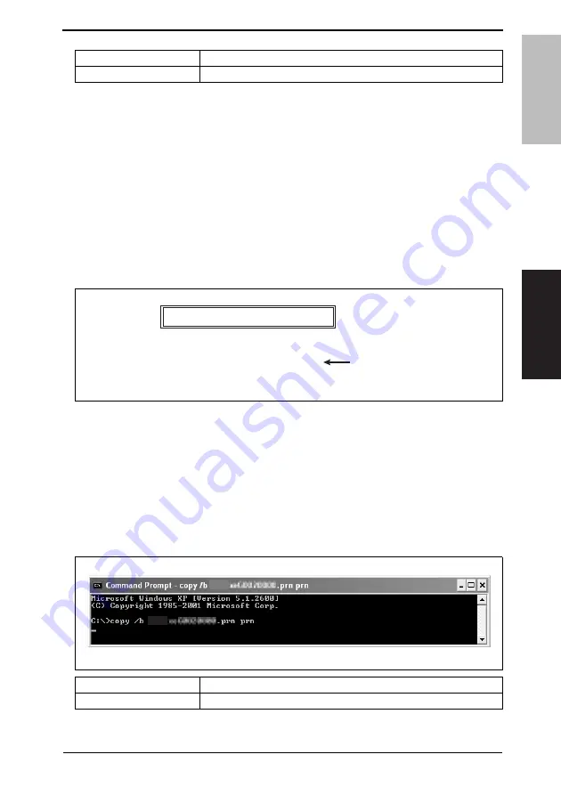
Execute the following command to start the transfer of the firmware data to the printer. 
(The screen shown below indicates that the firmware data resides on the C drive.)

Data to be upgraded

Command

FW upgraded data

> lpr -S XXX.XXX.XXX.XXX -P lp -o l 4039**********.prn

XXX.XXX.XXX.XXX : IP address of the machine
******

: File name of FW upgrade data

[2]

4039F2C519DA

PRINTER INFORMATION

DATE
TIME
CONTROLLER F/W
ENGINE F/W
BOOT F/W
TOTAL PAGE COUNT
SERIAL NUMBER

MM.DD.YYYY
HH.MM
403930G0120000(US)
403950F0150000(US)
403999G0110000
7
******

Data to be upgraded

Command

FW upgraded data

> copy /b 4039**********.prn prn

******: File name of FW upgrade data

4039F2E522DA

㪋㪇㪊㪐

㪋㪇㪊㪐

Summary of Contents for magicolor 7450

Page 1: ...SERVICE MANUAL 2006 05 2006 05 Ver 1 0 Ver 1 0 FIELD SERVICE magicolor 7450 magicolor 7450 ...

Page 2: ...ACHINE S 18 MEASURES TO TAKE IN CASE OF AN ACCIDENT S 20 Composition of the service manual C 1 Notation of the service manual C 2 magicolor 7450 Main Unit General 1 Maintenance 7 Adjustment Setting 77 Troubleshooting 177 Appendix 241 Lower Feeder Unit General 1 Maintenance 3 Adjustment Setting 27 Troubleshooting 31 Duplex Option General 1 Maintenance 3 Adjustment Setting 7 Troubleshooting 9 ...

Page 3: ...ii Blank Page ...

Page 4: ...rse of technical training and even after that for performing maintenance and control of the product properly Keep this Service Manual also for future service In this Service Manual each of three expressions DANGER WARNING and CAUTION is defined as follows together with a symbol mark to be used in a limited meaning When servicing the product the relevant works disassembling reassembling adjustment ...

Page 5: ...erformance and safety Such modifications are therefore strictly prohibited the points listed below are not exhaustive but they illustrate the reason ing behind this policy SAFETY WARNINGS Prohibited Actions DANGER Using any cables or power cord not specified by KMBT Using any fuse or thermostat not specified by KMBT Safety will not be assured leading to a risk of fire and injury Disabling fuse fun...

Page 6: ...cable having enough cur rent capacity and the cord set meets regulatory requirements for the area Use of inadequate cord set leads to fire or electric shock Attach power plug which meets the following criteria having configuration intended for the connection to wall outlet appropriate for the product s rated voltage and current and the plug has pin terminal s for grounding and meets regulatory req...

Page 7: ...er leads to the product connecting to inadequate power supply voltage current capacity grounding and may result in fire or electric shock If proper wall outlet is not available advice the customer to contact qualified electrician for the installation Plug the power cord into the dedicated wall outlet with a capacity greater than the maximum power consumption If excessive current flows in the wall ...

Page 8: ...o a risk of fire Check whether the power cord is damaged Check whether the sheath is damaged If the power plug cord or sheath is damaged replace with a new power cord with plug and connector on each end specified by KMBT Using the damaged power cord may result in fire or electric shock Do not bundle or tie the power cord Overheating may occur there leading to a risk of fire Check whether dust is c...

Page 9: ...not use an extension cable reel with the cable taken up Fire may result Prohibited Installation Places WARNING Do not place the product near flammable materials or vola tile materials that may catch fire A risk of fire exists Do not place the product in a place exposed to water such as rain A risk of fire and electric shock exists When not Using the Product for a long time WARNING When the product...

Page 10: ...ion before Servicing CAUTION Before conducting an inspection read all relevant docu mentation service manual technical notices etc and proceed with the inspection following the prescribed pro cedure using only the prescribed tools Do not make any adjustment not described in the documentation If the prescribed procedure or tool is not used the prod uct may break and a risk of injury or fire exists ...

Page 11: ... risk of elec tric shock exists Safety Checkpoints WARNING Check the exterior and frame for edges burrs and other damage The user or CE may be injured Do not allow any metal parts such as clips staples and screws to fall into the product They can short internal circuits and cause electric shock or fire Check wiring for squeezing and any other damage Current can leak leading to a risk of electric s...

Page 12: ...ng a lithium battery replace it with a new lith ium battery specified in the Parts Guide Manual Dispose of the used lithium battery using the method specified by local authority Improper replacement can cause explosion After replacing a part to which AC voltage is applied e g optical lamp and fixing lamp be sure to check the installa tion state A risk of fire exists Check the interlock switch and ...

Page 13: ... breathe excessive amounts or let the substances come into contact with eyes etc It may be stimulative If the substances get in the eye rinse with plenty of water immediately When symptoms are noticeable consult a physician Never throw the used cartridge and toner into fire You may be burned due to dust explosion Handling of Service Materials CAUTION Unplug the power cord from the wall outlet Drum...

Page 14: ...eaner at a time and take care not to spill any liquid If this happens immediately wipe it off A risk of fire exists When using any solvent ventilate the room well Breathing large quantities of organic solvents can lead to discomfort Handling of Service Materials CAUTION ...

Page 15: ...ar le constructeur Mettre au rebut les batteries usagées conformément aux instructions du fabricant Denmark ADVARSEL Lithiumbatteri Eksplosionsfare ved fejlagtig håndtering Udskiftning må kun ske med batteri af samme fabrikat og type Levér det brugte batteri tilbage til leverandøren Finland Sweden VAROlTUS Paristo voi räjähtää jos se on virheellisesti asennettu Vaihda paristo ainoastaan laitevalmi...

Page 16: ...t employs a Class 3B laser diode that emits an invisible laser beam The laser diode and the scanning polygon mirror are incorporated in the print head unit The print head unit is NOT A FIELD SERVICEABLE ITEM Therefore the print head unit should not be opened under any circumstances CAUTION Double pole neutral fusing ATTENTION Double pôle fusible sur le neutre semiconductor laser Maximum power of t...

Page 17: ...nd must be attached to laser products marketed in the United States All Areas Denmark CAUTION Use of controls adjustments or performance of procedures other than those specified in this manual may result in hazardous radiation exposure semiconductor laser Maximum power of the laser diode 10 mW Wavelength 775 800 nm CAUTION Use of controls adjustments or performance of procedures other than those s...

Page 18: ... användaren utsättas för osynlig laserstrålning som överskrider gränsen för laserklass 1 halvledarlaser Den maximala effekten för laserdioden 10 mW våglängden 775 800 nm VARO Avattaessa ja suojalukitus ohitettaessa olet alttiina näkymättomälle laser säteilylle Älä katso säteeseen VARNING Osynlig laserstråining när denna del är öppnad och spärren är urkopplad Betrakta ej stråien ADVERSEL Dersom app...

Page 19: ...S S 16 6 2 Laser Safety Label A laser safety label is attached to the inside of the machine as shown below 6 3 Laser Caution Label A laser caution label is attached to the outside of the machine as shown below 4039P0E506DA 4039P0C502DA ...

Page 20: ...and PC Drum be sure first to turn the printer OFF If the job requires that the printer be left ON take off your watch and ring and wear laser protective goggles A highly reflective tool can be dangerous if it is brought into the laser beam path Use utmost care when handling tools on the user s premises The Print Head is not to be disassembled or adjusted in the field Replace the Unit or Assembly i...

Page 21: ...care should be taken to avoid burns and electric shock WARNING INDICATIONS ON THE MACHINE 4039P0C505DA High voltage This area generates high voltage Be careful not to touch here when the power is turned ON to avoid get ting an electric shock High voltage This area generates high voltage Be careful not to touch here when the power is turned ON to avoid getting an electric shock ...

Page 22: ...gerous WARNING Do not burn used Imaging Units Toner expelled from the fire is dangerous CAUTION The area around the Fusing Unit is extremely hot Touching any part other than those indicated may result in burns You may be burned or injured if you touch any area that you are advised not to touch by any caution label Do not remove caution labels If any caution label has come off or soiled and therefo...

Page 23: ...of a serious accident has been received from a customer an on site evalua tion must be carried out quickly and KMBT must be notified 3 To determine the cause of the accident conditions and materials must be recorded through direct on site checks in accordance with instructions issued by KMBT 4 For reports and measures concerning serious accidents follow the regulations speci fied by every distribu...

Page 24: ...formation The basic configuration of each section is as follows However some options may not be applied to the following configuration Theory of Operation section Field Service section OUTLINE Explanation of system configuration product specifications unit configuration and paper path COMPOSITION OPERATION Explanation of configuration of each unit operating system and control system GENERAL Explan...

Page 25: ...ch company 1 PWB P Controller Board 2 magicolor 7450 Main unit 3 Microsoft Windows 95 Windows 95 Microsoft Windows 98 Windows 98 Microsoft Windows Me Windows Me Microsoft Windows NT 4 0 Windows NT 4 0 or Windows NT Microsoft Windows 2000 Windows 2000 Microsoft Windows XP Windows XP When the description is made in combination of the OS s mentioned above Windows 95 98 Me Windows NT 4 0 2000 Windows ...

Page 26: ...SERVICE MANUAL 2006 05 Ver 1 0 FIELD SERVICE Main Unit magicolor 7450 magicolor 7450 ...

Page 27: ... represents the number of times the revision has been made To indicate clearly a section revised show in the lower outside section of the correspond ing page A number within represents the number of times the revision has been made NOTE Revision marks shown in a page are restricted only to the latest ones with the old ones deleted When a page revised in Ver 2 0 has been changed in Ver 3 0 The revi...

Page 28: ...cedure Periodical check parts 13 3 4 1 Replacing the Tray 2 Feed Roller Standard 13 3 4 2 Replacing the Tray 2 Separation Roller 13 3 4 3 Replacing the Tray 1 Feed Roller Bypass 14 3 4 4 Replacing the Tray 1 Separation Roller 16 3 4 5 Replacing the Waste Toner Bottle 17 3 4 6 Replacing the Ozone Filter 18 3 4 7 Replacing the Deodorant Filter 18 3 4 8 Replacing the Dust Filter Vertical Conveyance 1...

Page 29: ...6 3 2 Rear Right Cover Rear Cover 38 6 3 3 Tray 1 Left Cover Tray 1 Right Cover Tray 1 Upper Cover 39 6 3 4 Front Door 39 6 3 5 Exit Tray 40 6 3 6 Control Panel 41 6 3 7 Tray 2 42 6 3 8 Front Cover 44 6 3 9 Controller Board PWB P 46 6 3 10 Memory DIMM0 47 6 3 11 Hard Disk Kit Option 48 6 3 12 Mechanical Control Board PWB M 48 6 3 13 RTC Board PWB R 51 6 3 14 DC Power Supply PU1 51 6 3 15 High Volt...

Page 30: ...r 75 6 4 8 Area around the Waste Toner Collecting Port 76 Adjustment Setting 7 How to Use the Adjustment Section 77 8 Description of the Control Panel 78 8 1 Control Panel Display 78 8 1 1 Parts of the Control Panel Display 78 8 1 2 Message structure 79 8 1 3 Normal messages 80 8 1 4 Menu 84 8 1 5 Operator Call messages 85 8 1 6 Service Call messages 86 8 1 7 Help screen 87 8 2 List of Control Pan...

Page 31: ...TION 116 9 5 6 COLOR SEPARATION 117 9 6 CAMERA DIRECT 117 9 6 1 PAPER SOURCE 117 9 6 2 LAYOUT 118 9 6 3 PAPER MARGIN 118 9 6 4 IMAGE QUALITY 118 9 7 INTERFACE MENU 119 9 7 1 JOB TIMEOUT 119 9 7 2 ETHERNET 120 9 7 3 CAMERA DIRECT 122 9 8 SYS DEFAULT MENU 122 9 8 1 LANGUAGE 122 9 8 2 EMULATION 123 9 8 3 PAPER 125 9 8 4 STARTUP OPTIONS 127 9 8 5 AUTO CONTINUE 127 9 8 6 HOLD JOB TIMEOUT 127 9 8 7 ENER...

Page 32: ...2 Mechanical adjustment 173 12 1 Mechanical adjustment of the Tray 1 173 12 1 1 Adjustment of the Tray 1 Paper Size Unit 173 12 2 PH Unit Mechanical Adjustment 175 12 2 1 Skew Adjustment 175 Troubleshooting 13 Jam Display 177 13 1 Misfeed Display 177 13 2 Misfeed Display Resetting Procedure 177 13 3 Sensor layout 178 13 4 Solution 179 13 4 1 Initial Check Items 179 13 4 2 Misfeed at Fusing Exit se...

Page 33: ... 0094 2nd Image Transfer Roller Separation 196 14 3 14 0096 Transfer Belt Separation 196 14 3 15 0301 Polygon Motor C failure to turn 197 14 3 16 0302 Polygon Motor M failure to turn 197 14 3 17 0303 Polygon Motor Y failure to turn 197 14 3 18 0304 Polygon Motor K failure to turn 197 14 3 19 0311 Laser malfunction Cyan 197 14 3 20 0312 Laser malfunction Magenta 197 14 3 21 0313 Laser malfunction Y...

Page 34: ... Cyan Imaging Unit EEPROM access error 203 14 3 49 13D2 Magenta Imaging Unit EEPROM access error 203 14 3 50 13D3 Yellow Imaging Unit EEPROM access error 203 14 3 51 13D4 Black Imaging Unit EEPROM access error 203 14 3 52 13D9 Cyan Toner Cartridge EEPROM access error 204 14 3 53 13DA Yellow Toner Cartridge EEPROM access error 204 14 3 54 13DB Magenta Toner Cartridge EEPROM access error 204 14 3 55...

Page 35: ...3 2 Monocolor white lines in Main Scan Direction white bands in Main Scan Direction colored lines in Main Scan Direction colored bands in Main Scan Direction 216 16 3 3 Monocolor uneven density in sub scan direction 217 16 3 4 Monocolor uneven density in main scan direction 218 16 3 5 Monocolor low image density 219 16 3 6 Monocolor gradation reproduction failure 221 16 3 7 Monocolor foggy backgro...

Page 36: ...pots 235 16 3 21 4 Color colored spots 236 16 3 22 4 Color poor fusing performance offset 237 16 3 23 4 Color brush effect blurred image 238 16 3 24 4 Color back marking 239 16 3 25 4 Color uneven image 240 Appendix 17 Parts layout drawing 241 17 1 Main unit 241 17 1 1 Engine section 241 17 1 2 Tray 1 Tray 2 245 17 2 Lower Feeder Unit Option 246 17 3 Duplex Option Option 247 18 Connector layout dr...

Page 37: ...magicolor 7450 General Maintenance Adjustment Setting Troubleshooting Appendix Field Service Ver 1 0 May 2006 x Blank Page ...

Page 38: ... Use the Desk or the paper feed cabinet without fail when installing on the floor in order to keep the function and quality of the unit 1 Main Body 5 Caster Base 2 Duplex Option 6 DIMM 3 Banner Tray 7 Hard Disk Kit 4 Lower Feeder Unit 500 sheets 8 Compact Flash Card 4039T1J101AA 1 4 6 5 2 3 7 8 Tray 3 Tray 4 Tray 5 ...

Page 39: ...ration system Tray 2 Small diameter roller separation system Exposure System Four multi array PH unit system Two beam LD polygon mirror exposure system for Y M C and K 8 beams in total Exposure Density 600 dpi 600 dpi 4 bit Developing System HMT developing system Charging System DC comb electrode Scorotron system Image Transfer System Intermediate transfer belt system Paper Separating System Selec...

Page 40: ... Paper 91 to 256 g m2 24 25 to 68 lb OHP Post card Envelope Label sheet 55 5 mm sec Printing Speed for Multi print Cycle crosswise feeding Monochrome print Color print A4 1 sided 25 prints min 2 sided 23 5 prints min 8 5 x 11 1 sided 24 5 prints min 2 sided 23 0 prints min Print Paper Size Tray1 Tray2 Metric Area A3 to A5 B6R A3 Wide 12 25 18 A6R Thick Paper Postcards Inch Area 11 17 to 5 5 8 5 A3...

Page 41: ...4 25 to 40 lb Thick paper 2 151 to 209 g m2 40 25 to 55 5 lb Thick paper 3 210 to 256 g m2 55 75 to 68 lb 1 10 sheets or less Postcards Envelopes Labels 50 sheets or less Print paper dimensions Width 90 to 311 mm 3 5 to 12 25 inch 90 to 311 mm 3 5 to 12 25 inch 140 to 297 mm 5 5 to 11 75 inch Length 140 to 457 mm 5 5 to 18 inch 140 to 457 mm 5 5 to 18 inch 182 to 432 mm 7 25 to 17 inch Long size p...

Page 42: ... of 20 h Levelness Difference between front and back right and left should be 1 degree or under Type Built in PS PCL controller RAM Standard 256 MB max 1 024 MB HDD 40 GB Option Compact Flash Card 256 MB or 512 MB commercially available Interface Ethernet 10 Base T 100 Base TX 1000 Base T USB 2 0 High speed IEEE 1284 Parallel PictBridge digital camera direct connection Supported Protocols TCP IP I...

Page 43: ...2 Product specifications Field Service Ver 1 0 May 2006 6 magicolor 7450 General Blank Page ...

Page 44: ...at the same time No Class Parts to be replaced Cycle Clean Replace Descriptions 1 Processing sections Imaging Unit C M Y 30 K 2 Imaging Unit K 50 K 3 Dust filter Cooling Fan 18 K 1 4 Toner cartridge Y M C After consumable 6 K 12 K 5 Toner cartridge Y M C Prepackaged 3 K 6 Toner cartridge K After consumable 7 5 K 15 K 2 7 Toner cartridge K Prepackaged 3 K 8 Fusing section Deodorant filter 7 5 K 15 ...

Page 45: ...ss Parts to be replaced Quantity Check Clean Replace Lubrica tion Descrip tions 1 Overall Paper feed and image conditions 2 Appearance 3 Tray 1 2 Feed Roller 1 4 Separation Roller 1 No Class Parts to be replaced Quantity Check Clean Replace Lubrica tion Descrip tions 1 Overall Paper feed and image conditions 2 Appearance 3 Lower Feeder Unit Pick up Roller 1 4 Feed Roller 1 5 Separation Roller 1 ...

Page 46: ...t the same time when the Waste Toner Bottle is replaced 4 220 240 V areas only 5 110 V to 120 V areas only 6 A waste toner full condition is detected with detecting the actual waste toner emissions No Classification Parts name Qua ntity Actual durable cycle Parts No Descriptions 1 Tray 2 Tray 2 Feed Roller Standard 1 200 K 4034 3012 2 Tray 2 Separation Roller 1 200 K 4034 0151 3 Tray 1 Tray 1 Feed...

Page 47: ...magicolor 7450 Maintenance B Option 2 See the Lower Feeder Unit Service Manual No Classification Parts name Qua ntity Actual durable cycle Parts No Descriptions 1 Lower Feeder Unit Feed Roller 1 300 K 1 2 Separation Roller 1 300 K 3 Pick up Roller 1 300 K ...

Page 48: ...urs through which the Fusing Drive Motor has turned translated to a cor responding value of the number of prints made and the value whichever reaches the life specification value is detected When the maximum number of printed pages is reached the print is inhibited 120 K 150 K Transfer Belt It is detected by counting the number of hours the Transfer Belt turns The printing is prohibited when it re...

Page 49: ...the Table given below are met They can be more or less depending on the machine operating conditions of each individual user Item Description Job Type Monochrome Making 3 prints per job Color Making 3 prints per job Paper Size A4 Letter Color Ratio Black to Color 1 1 CV M Black 1 500 Color 1 500 Original Density B W 5 for each color 5 for Monochrome No of Operating Days per Month 20 days Main Powe...

Page 50: ...the C clip 2 from the Tray 2 Feed Roller Standard Assy 3 4 Remove the shaft for the Tray 2 Feed Roller Standard Assy 3 from the front Bushing 5 Snap off the C clip 4 one collar 5 and remove the Tray 2 Feed Roller Standard 6 6 To reinstall reverse the order of removal NOTE Replace the Tray 2 Feed Roller Standard and Tray 2 Separation Roller at the same time 3 4 2 Replacing the Tray 2 Separation Rol...

Page 51: ... E ring 8 and the Tray 2 Separation Roller Assy 9 5 To reinstall reverse the order of removal NOTE Replace the Tray 2 Feed Roller Standard and Tray 2 Separation Roller at the same time 3 4 3 Replacing the Tray 1 Feed Roller Bypass 1 Remove the Multi Bypass Unit See P 57 2 Snap off the E ring 1 and remove Tray 1 Paper Feed Clutch 2 3 Remove the Gear 3 3 7 6 4 5 4038F2C003DB 4037F2C509DA 8 9 1 2 403...

Page 52: ... 4 and remove the Bearing 5 5 Snap off two C ring 6 and remove the Bearing 7 6 Remove the Tray 1 Feed Roller Bypass 8 7 To reinstall reverse the order of removal NOTE Replace the Tray 1 Feed Roller Bypass and the Tray 1 Separation Roller at the same time 4 5 4038F2C006DB 6 7 4038F2C007DB 8 4038F2C008DB ...

Page 53: ...move the Ground terminal 2 3 Remove the Screw 3 and remove the Tray 1 Separation Roller Assy 4 4 Snap off the C clip 5 and remove the spring 6 and the guide plate 7 Remove the Tray 1 Separation Roller 8 5 To reinstall reverse the order of removal NOTE Replace the Tray 1 Feed Roller Bypass and the Tray 1 Separation Roller at the same time 1 2 4038F2C009DA 3 4 4038F2C010DA 4038F2C502DA 5 7 6 8 ...

Page 54: ...n the vicinity of the toner collecting port do not tilt the Waste Toner Bottle when removing it Do not leave the Waste Toner Bottle in a tilted condition after removing it 4 Clean the surface around the waste toner collecting port See P 76 5 Remove the Waste Toner Bottle from its box and remove the packing material 6 Set the Waste Toner Bottle 3 in place 7 Close the Front Door NOTE Replace the Dus...

Page 55: ...he hook take out the Deodorant Filter 1 NOTE The Deodorant Filter is supplied with the Toner Cartridge Black Replace it when replacing the Toner Cartridge Black 3 4 8 Replacing the Dust Filter Vertical Conveyance 1 If the optional Automatic Duplex Unit is mounted remove it See Duplex Option Service Manual 2 Remove the Dust Filter Vertical Con veyance 1 NOTE The Dust Filter Vertical Conveyance is s...

Page 56: ...cedure 1 Open the Front Door and turn OFF the Main Power Switch 2 Open the Right Door 3 Unlock the Lock levers 1 at two places 4 Holding onto the Lock levers 1 at two places remove the Transfer Roller 2 B Reinstallation Procedure 1 Holding onto the Lock levers 1 at two places mount the Transfer Roller 2 2 Lock the Lock levers 1 at two places 3 Close the Right Door NOTE Make sure that the door is l...

Page 57: ... the Lock of the Transfer Belt 2 3 Hold the both sides and lift it to take out the Transfer Belt 3 a little 4 Hold the position 4 as shown in the left and remove the Transfer Belt 5 NOTE Do not touch the surface of the Transfer Belt Cover the Transfer Belt with some thing such shade cloth to protect its surface from dust or foreign matter 1 2 4039F2C005DA 3 4039F2C006DA 4 5 4 4039F2C007DA ...

Page 58: ...r Belt with some thing such shade cloth to protect its surface from dust or foreign matter 2 Install the Transfer Belt with two Screws 2 NOTE Replace the Transfer Roller the Ozone Filter and the Dust Filter Ver tical Conveyance which are sup plied with the Transfer Belt at the same time 3 Close the Right Door 4 Reinstall the Imaging Unit and the Waste Toner Bottle 5 Close the Front Door 6 Turn ON ...

Page 59: ...Removal Procedure 1 Open the Front Door 2 Pressing the Toner Cartridge Lock Claw 1 pull it toward 3 Pull the Toner Cartridge 2 toward to remove it B Reinstallation Procedure 1 Take out the new Toner Cartridge 1 from the unitary packing box and shake it well up and down 5 to 10 times 4038F2C560DA 1 4038F2C538DA 2 4038F2C539DA 1 ...

Page 60: ... Make sure the Toner Cartridge is inserted all the way When replacing the Toner Cartridge black replace the Deodorant Filter supplied with it at the same time 3 5 4 Replacing the Imaging Unit C M Y K A Removal Procedure 1 Turn OFF the Main Power Switch and open the Front Door 2 Unplug the power cord 3 Press the unlocking knob 1 of Imaging Unit 4 Pull out the Imaging Unit 2 and remove it from main ...

Page 61: ...ly 2 Take the Imaging Unit 2 out from the black plastic bag 3 3 Peel off the Tape 4 so that the Mounting Bracket 5 can be removed Then remove the Mount ing Bracket 5 NOTE Since the Imaging Unit is highly susceptible to light keep it shielded from light up to the time it is installed Carefully unseal the plastic bag black If the Imaging Unit is packed in the plastic bag black again seal the package...

Page 62: ...tall them by fitting the blue label position of Imaging Unit and one of the machine Do not allow the Imaging Unit to become tilted while installing them into the Main Unit as damage to the PC Drum can result 6 Pull out the PC Drum protective sheet 8 while pressing the Imaging Unit 7 Insert the Imaging Unit all the way NOTE Make sure that the Imaging Unit is inserted all the way 8 Plug in the power...

Page 63: ...lacing the Fusing Unit CAUTION Before replacing the Fusing Unit ensure that it has had time to cool down 1 Turn OFF the Main Power Switch and unplug the power cord from the power outlet then wait for about 20 minutes 2 Open the Front Door 3 Remove two Claws 1 and remove the Exit Tray Connector protective cover 2 4 Disconnect the Connector 3 4039F2C507DB 9 1 2 4039F2C010DA 3 4039F2C011DA ...

Page 64: ... Remove the Screw 4 and remove the Connector protective cover 5 6 Disconnect two Connectors 6 7 Open the Right Cover 8 Open the Fusing Unit Cover 9 Remove two Screws 7 and remove the Fusing unit 8 NOTE Do not leave the Right Door open 4 5 4039F2C012DA 6 4039F2C013DA 7 8 4039F2C014DA ...

Page 65: ...e Ver 1 0 May 2006 28 magicolor 7450 Maintenance 4 Service tool 4 1 CE Tool list Tool name Shape Personnel Parts No Remarks PH Window Cleaning Jig 1 4038 2083 xx PH Window Cleaning Jig Pad 1 4038 2084 xx 4038F2C557DA 4038F2C558DA ...

Page 66: ...ideration when the T C is used under the conditions of B W ratio 5 for each color 4 2 3 Waste Toner Bottle Replace the Dust Filter Cooling Fan supplied with the Waste Toner Bottle at the same time 1 A waste toner full condition is detected with detecting the actual waste toner emissions See P 12 4 2 4 Maintenance Kit There is no setting for the Maintenance Kit Parts name Replacing period IU Black ...

Page 67: ...cable over category 5e If a cable that is not compatible with 1000BASE T is used communication may not be made correctly Check that printing is available over the network 2 From the Menu select PRINT MENU CONFIGURATION PG and execute the function Then check the IP address 1 of the machine See P 101 3 Copy the firmware data and upgrading program to any directory on the PC 4 Start the Command Prompt...

Page 68: ... the machine to the PC using a parallel cable NOTE Check that printing is available through the parallel cable 2 Copy the firmware data and upgrading program to any directory on the PC 3 Start the Command Prompt and go to the directory in which the firmware data is stored 4 Execute the following command to start the transfer of the firmware data to the printer The screen shown below indicates that...

Page 69: ...xecute the function Then check that the firmware 2 has been upgraded See P 101 C What to do if the firmware upgrade fails Use the following procedure if the firmware upgrade process is suspended for any reason The printer cannot start until the firmware upgrade process completes correctly 1 Turn OFF the Main Power Switch of the printer 2 Connect the machine to the PC using a parallel cable 3 Turn ...

Page 70: ...firmware data resides on the C drive 8 Wait until all of the data is sent This takes approximately 2 minutes While the data is being sent FIRMWARE UPDATE and RECEIVING DATA are alter nately displayed on the screen NOTE Never turn the printer power switch OFF and ON while data is being sent 9 After the data has finished being sent the following message appears on the screen of the Command Prompt Da...

Page 71: ...layed 12 Turn the printer s Main Switch OFF and then ON 13 After the printer has restarted check that a READY message is displayed 14 From the Menu select PRINT MENU CONFIGURATION PG and execute the function Then check that the firmware 2 has been upgraded See P 101 4138F2C010DA FIRMWARE UPDATE WRITING DATA XX 4138F2C011DA FIRMWARE UPDATE TO CONTINUE TURN OFF THEN ON 2 4039F2C519DA PRINTER INFORMA...

Page 72: ...when two or more screws are used for a single part only one repre sentative screw may be marked with the red paint C Variable resistors on board NOTE Do not turn the variable resistors on boards for which no adjusting instructions are given in Adjustment Setting D Removal of PWBs CAUTION When removing a circuit board or other electrical component refer to Handling of PWBs and follow the correspond...

Page 73: ... 42 13 Front Cover P 44 14 Board and etc Controller Board P 46 15 Memory DIMM0 P 47 16 Hard Disk Kit option P 48 17 Mechanical Control Board P 48 18 RTC Board P 51 19 DC Power Supply P 51 20 High Voltage Unit P 53 21 Tray 2 Paper Size Board P 54 22 PH Interface Board P 55 23 Unit Multi Bypass Unit P 57 24 PH Unit P 58 25 Transport Drive Assy P 62 26 Hopper Drive Assy P 64 27 Right Door Assy P 65 2...

Page 74: ... 1 PH PH Window P 72 2 Processing section Transfer Belt P 73 3 Tray 2 Tray 2 Feed Roller Standard P 73 4 Tray 2 Separation Roller P 73 5 Tray 1 Tray 1 Feed Roller Bypass P 74 6 Tray 1 Separation Roller P 74 7 Conveyance section Registration Roller P 75 8 Image transfer section Area around the Waste Toner Collecting Port P 76 ...

Page 75: ...ht Door 2 3 Remove two Screws 3 and remove the Upper Front Cover 4 4 Remove two Screws 5 and remove the Rear Left Cover 6 5 Remove two Screws 7 and remove the Front Left Cover 8 6 3 2 Rear Right Cover Rear Cover 1 Open the Right Door 1 2 Remove three Screws 2 and remove the Rear Right Cover 3 3 Remove nine Screws 4 and remove the Rear Cover 5 1 2 3 4 5 6 7 8 4039F2C015DA 1 2 3 4 4 4 5 4039F2C016DA...

Page 76: ... the tab 1 and remove the Tray 1 Left Cover 2 2 Remove the Screws 3 and remove the Tray 1 Right Cover 4 3 Remove the Tray Extension 5 4 Remove two Screws 6 and remove the Tray 1 Upper Cover 7 6 3 4 Front Door 1 Open the Front Door 2 Remove the Screw 1 each to remove the Right and Left Stoppers 2 1 2 3 4 5 6 7 4039F2C017DA 1 2 4038F2C038DB ...

Page 77: ...Pins 3 to remove the Front Door 4 6 3 5 Exit Tray 1 Remove the Rear Left Cover Front Left Cover and Rear Cover See P 38 2 Remove the Dust Filter Cooling Fan 1 3 Open the Upper Fusing Cover 2 4 Remove two Claws 3 and remove the Upper Fusing Cover 2 3 4 4 4038F2C039DA 1 4039F2C018DA 2 3 3 4039F2C019DA ...

Page 78: ...5 Disconnect the Connector 4 6 Remove two Screws 5 and remove the Exit Sensor Assy 6 7 Remove three Screws 7 and remove the Exit Tray 8 6 3 6 Control Panel 1 Remove the Upper Front Cover See P 38 2 Remove two Screws 1 4 5 6 4039F2C020DA 7 8 4039F2C021DA 1 1 4039F2C022DA ...

Page 79: ...2006 42 magicolor 7450 Maintenance 3 Remove the Screw 2 and remove the Ground terminal 3 4 Disconnect the Connector 4 and remove the Control Panel 5 6 3 7 Tray 2 1 Slide out the Tray 2 1 2 3 4039F2C023DA 4 5 4039F2C024DA 1 4039F2C025DA ...

Page 80: ...0 May 2006 6 Other 43 magicolor 7450 Maintenance 2 Loosen the screw 2 hold two tabs 3 and remove the spacer 4 3 Slide out the Tray 2 6 while press ing the Slide Locks 5 at both ends 3 2 4038F2C609DA 4 5 6 5 6 4037F2C044DB ...

Page 81: ... 22 4 Remove the Waste Toner Bottle See P 17 5 Remove the imaging Units C M Y K See P 23 NOTE After the Imaging Unit has been removed from the main unit wrap it in the light shielding cloth and store it in a dark place DO NOT leave the Imaging Unit exposed to light for a extended period of time as it will become damaged 6 Remove the Screw 1 and remove the Connector protective cover 2 7 Disconnect ...

Page 82: ...ice Ver 1 0 May 2006 6 Other 45 magicolor 7450 Maintenance 8 Disconnect two Connectors 4 9 Remove four Screws 5 10 Unhook six tabs 6 and remove the Front Cover 7 4 4038F2C053DA 5 5 4039F2C026DA 6 6 7 4039F2C027DA ...

Page 83: ...icolor 7450 Maintenance 6 3 9 Controller Board PWB P 1 Remove the Rear Left Cover See P 38 2 Remove the Memory 1 3 Remove all the Connectors and Flat Cables on the Controller Board 4 Remove three Screws 2 1 4039F2C040DB 4039F2C041DA 2 4039F2C042DA ...

Page 84: ...Maintenance 5 Remove nine Screws 3 and remove the Controller Board 4 NOTE When the Controller Board is replaced make sure to update the firmware 6 3 10 Memory DIMM0 1 Remove the Rear Left Cover See P 38 2 Remove the Memory 1 3 3 4 4039F2C043DA 1 4039F2C040DB ...

Page 85: ... 38 2 Disconnect the Connector 1 and remove the Hard Disk 2 6 3 12 Mechanical Control Board PWB M 1 Remove the Exit Tray See P 40 2 Remove the Controller Board See P 46 3 Remove six Screws 1 and remove the Interface Cover 2 4 Remove two Screws 3 and remove the Flat Cable Cover 4 4039F2C509DA 1 2 1 1 2 4039F2C028DA 3 4 4039F2C029DA ...

Page 86: ...5 Remove eleven Screws 5 and remove the Controller Board mount ing bracket 6 6 Remove all the Connectors and Flat Cables on the Mechanical Control Board 7 Remove six Screws 7 and remove the Mechanical Control Board 8 5 5 5 5 6 4039F2C030DA 4039F2C031DA 7 7 8 4039F2C032DA ...

Page 87: ... Mechanical Control Board NOTE When the Parameter Chip IC6 is mounted precisely fit the direc tions of each A NOTE When the Control Board is to be replaced rewriting the Firmware to the latest one NOTE When mounting the Mechanical Control Board mount it so that the Ferrite Core 9 will be between two wire saddles Be careful that the Ferrite Core 9 will not go over the Control Board 4037F2C061DB 403...

Page 88: ...ount ing bracket See P 46 2 Disconnect the Connector 1 3 Remove two Screws 2 and remove the RTC Board 3 6 3 14 DC Power Supply PU1 1 Remove the Exit Tray See P 40 2 Remove the Control Panel See P 41 3 Disconnect the Connector 1 and remove the Harness 3 from the Edge cover 2 1 4039F2C034DA 2 3 4039F2C035DA 1 2 3 4039F2C036DA ...

Page 89: ...450 Maintenance 4 Remove nine Screws 4 and remove the protective sheet of DC Power Supply 5 5 Remove all the Connectors on the DC Power Supply 6 Remove eight Screws 6 and remove the DC Power Supply 7 4 4 4 4 5 4039F2C037DA 4039F2C038DA 6 6 7 4039F2C039DA ...

Page 90: ...our Connectors 1 3 Remove five Screws 2 and the tab 3 and remove the High Voltage Unit 4 NOTE When installing the High Voltage Unit make sure that the terminal end surely contacts NOTE When installing the High Voltage Unit make sure that the claw 5 shown in the left illustration is surely set up 1 4038F2C085DA 2 2 3 4 4038F2C086DA 5 4038F2C087DA ...

Page 91: ... 3 16 Tray 2 Paper Size Board PWB I 1 Slide out the Tray 2 2 Remove the Rear Cover See P 38 3 Remove two Screws 1 and Connec tor 2 and remove the Tray 2 Paper Size Board Assy 3 4 Remove the Lever 4 5 Remove the Tray 2 Paper Size Board 5 1 2 3 4038F2C088DA 4 5 4038F2C516DA ...

Page 92: ... Front Cover See P 44 2 Remove the Transfer Belt See P 20 3 Remove two Screws 1 and remove the Front Right Cover 2 4 Remove seven Screws 3 and remove the Right Door Switch Assy 4 5 Remove the Screw 5 each and remove the Imaging Unit contact Assy 6 of each color 1 2 4038F2C097DA 3 3 4 4038F2C098DA 5 6 4038F2C099DA ...

Page 93: ...e two Screws 7 each and remove the Imaging Unit Roll Assy 8 of each color 7 Remove all the Connectors and the Flat Cables on the PH Interface Board 8 Remove two Screws 9 and six tabs 10 and remove the PH Interface Board 11 7 8 4038F2C100DA 4038F2C101DA 9 9 11 10 10 4038F2C102DB ...

Page 94: ...move the Tray 1 Right Cover and the Tray 1 Left Cover See P 39 2 Disconnect five Connectors 1 3 Remove four Screws 2 and remove the Multi Bypass Unit 3 NOTE When installing the Multi Bypass Unit fit the position of dowel shown in the left illustration 1 1 4038F2C103DA 2 2 3 4038F2C104DA 4038F2C105DA ...

Page 95: ... 44 2 Remove the Transfer Belt See P 20 3 Remove the Screw 1 and discon nect the Connector 2 respectively and remove three Imaging Unit Guide rails 3 4 Disconnect the Flat Cable 4 and the Connector 5 of the PH Unit Black 5 Unhook the tab 6 and remove the Gear 7 of the PH Unit Black 1 2 3 4038F2C106DA 4 5 4038F2C107DA 7 6 4038F2C108DB ...

Page 96: ...r other image troubles 7 Remove the PH Unit Black Move the front side of the PH Unit to left a little and remove the boss 9 from the locating hole 10 Lift up the front side of the PH Unit a little Remove the boss 11 at the rear side of the PH Unit from the locating hole 12 NOTE Since the back of the PH Unit is pushed to the right with the two plate springs 13 remove it by tilting the backside of t...

Page 97: ...ure 1 Fit the back of the PH Unit 1 into the plate spring 2 of installation plate 2 Push the PH Unit 3 along the right side line of PH Unit installation plate all the way and fit it into the plate spring 4 3 Make sure that the two bosses 5 at front and rear side of the PH Unit fit in the locating hole 6 4037F2C112DB 14 4037F2C113DB 1 2 4037F2C114DA 5 6 5 6 4 3 ...

Page 98: ...ear claw is fit in 6 Connect the Connector and the Flat Cable NOTE Make sure the Harness is installed along with the Harness guide 7 Follow the same procedures to install all the PH Units 8 Install the Imaging Unit Guide Rail 9 NOTE Make sure that the two claws 10 at rear end of the rail are fit in the locating hole on the main unit 9 Reinstall the Transfer Belt 10 Reinstall the Front Cover 11 Mak...

Page 99: ... See P 53 3 Remove the Color Developing Motor See P 68 4 Remove the Color PC Drum Motor See P 68 5 Remove the Main Motor See P 69 6 Remove three Screws 1 and remove the Reinforcement plate 2 of the Right Door and spring 3 7 Remove the Shoulder Screw 4 8 Remove two Screws 5 and remove the Metal blanking plate 6 1 2 3 4038F2C118DA 4 4038F2C119DA 5 6 4038F2C120DA ...

Page 100: ...remove the Rear Handle Assy 9 10 Disconnect the Connector 10 11 Remove the Harnesses 12 from five Wire Saddles 11 12 Remove eight Screws 13 and remove the Transport Drive Assy 14 NOTE The Screw is fixed at the position with the triangle markers 7 7 8 9 7 4038F2C121DA 10 11 11 12 12 4038F2C122DA 13 13 14 4038F2C123DA ...

Page 101: ...450 Maintenance 6 3 21 Hopper Drive Assy 1 Remove the Transfer Drive Assy See P 62 2 Disconnect seven Connectors 1 3 Remove the Harness from four Wire Saddles 2 4 Remove two Screws 3 and remove the Duct 4 1 1 1 4038F2C124DB 2 4038F2C125DA 3 4 4038F2C126DA ...

Page 102: ...the Hopper Drive Assy 7 6 3 22 Right Door Assy 1 Remove the Rear Cover See P 38 2 Remove the High Voltage Unit See P 53 3 Open the Right Door 4 Remove three Screws 1 and remove the Reinforcement plate 2 of the right door and spring 3 5 Remove the Shoulder Screw 4 5 5 6 6 7 4038F2C127DA 1 2 3 4039F2C510DA 4 4039F2C511DA ...

Page 103: ...r 7450 Maintenance 6 Remove two Screws 5 and remove the Metal blanking plate 6 7 Remove five Screws 7 and the Connector 8 and remove the Rear Handle Assy 9 8 Disconnect four Connectors 10 5 6 4039F2C512DA 7 7 8 9 7 4039F2C513DA 10 10 10 10 4039F2C514DA ...

Page 104: ...ve the Front Right Cover 12 12 Remove the Screw 13 and remove the Shaft 14 13 Remove the Right Door Assy 15 6 3 23 Cooling Fan Motor 2 M22 Assy 1 Remove the Rear Cover See P 38 2 Remove the Exit Tray See P 40 3 Remove the Connector 2 and two Screws 1 and remove the Cooling Fan Motor 2 M22 Assy 3 12 11 11 4039F2C515DA 13 15 14 4039F2C516DA 1 2 3 4039F2C526DA ...

Page 105: ...the Color Developing Motor 3 6 3 25 Color PC Drum Motor M2 1 Remove the Cooling Fan Motor 2 Assy See P 67 2 Remove the Connector 1 and four Screws 2 and remove the Color PC Drum Motor 3 6 3 26 Toner Supply Motor C K M7 1 Remove the Cooling Fan Motor 2 Assy See P 67 2 Remove the Connector 1 and two Screws 2 and remove the Toner Supply Motor C K 3 1 2 3 4038F2C149DA 1 2 3 4038F2C150DA 1 3 2 4038F2C1...

Page 106: ...nd two Screws 2 and remove the Toner Supply Motor Y M 3 6 3 28 Main Motor M1 1 Remove the Rear Cover See P 38 2 Remove the Connector 1 and four Screws 2 and remove the Main Motor 3 6 3 29 Fusing Drive Motor M4 1 Remove the Rear Cover See P 38 2 Remove the Connector 1 and two Screws 2 and remove the Fusing Drive Motor 3 2 1 3 4038F2C152DA 1 2 3 4039F2C517DA 1 2 3 4039F2C518DA ...

Page 107: ...w 1 and remove the Plate spring 2 4 Remove the Shoulder Screw 3 and the Screw 4 5 Remove the Vertical transport unit 5 in manner of the left illustration NOTE Since multiple Connectors are con nected to the backside of the Verti cal Transport Assy do not pull it by force 6 Remove the Claws 6 of both sides and remove the Sensor cover 7 NOTE Use care not to miss the spring 8 1 2 4038F2C169DA 5 3 4 4...

Page 108: ...ther 71 magicolor 7450 Maintenance 7 Remove two Screws 9 and Connec tor 10 and remove the IDC Regis tration Sensor 1 11 8 Repeat the step 6 and 7 and remove the IDC Registration Sensor 2 rear side 12 9 10 11 4038F2C172DA 12 4038F2C173DA ...

Page 109: ... the cleaning procedure represents the isopropyl alcohol 6 4 1 PH Window 1 Open the Front Door 2 Remove the PH Window Cleaning Jig 1 3 Insert the PH Window Cleaning Jig 2 to the cleaning port 3 and clean it by putting the jig back and forth a couple times NOTE Clean every PH Window of CMYK 4038F2C547DA 1 4038F2C548DA 3 2 ...

Page 110: ...water When solvent is used to dampen a cloth do not use the ones other than shown below isopropyl alcohol ethyl alcohol PPC Cleaner Sol mix AP 7 6 4 3 Tray 2 Feed Roller Standard 1 Slide out the Tray 2 2 Using a soft cloth dampened with alcohol wipe the Tray 2 Feed Roller Standard 1 clean of dirt 6 4 4 Tray 2 Separation Roller 1 Slide out the Tray 2 2 Remove two Screws 1 and remove the Tray 2 Pape...

Page 111: ...ler 3 clean of dirt 6 4 5 Tray 1 Feed Roller Bypass 1 Remove the Multi Bypass Unit See P 57 2 Using a soft cloth dampened with alcohol wipe the Tray 1 Feed Roller Bypass 1 6 4 6 Tray 1 Separation Roller 1 Remove the Multi Bypass Unit See P 57 2 Remove the Screws 1 and remove the Ground terminal 2 3 4038F2C176DA 1 4038F2C177DA 1 2 4038F2C009DA ...

Page 112: ... Tray 1 Separation Roller Assy 4 4 Using the soft cloth dampened with alcohol wipe the Tray 1 Paper Sepa ration Roller 5 6 4 7 Registration Roller 1 Open the Right Door 2 Using a soft cloth dampened with alcohol wipe the Registration Roll ers 1 clean of dirt 3 4 4038F2C010DA 5 4038F2C178DA 1 4038F2C017DA ...

Page 113: ...Maintenance 6 4 8 Area around the Waste Toner Collecting Port 1 Remove the Waste Toner Bottle See P 17 2 Wipe the areas around the Waste Toner Collecting Port 1 clean of spilled toner and dirt using a soft cloth dampened with water or alco hol 1 4039F2C001DA ...

Page 114: ...high humidity direct sunlight direct ventilation etc Does the original have a problem that may cause a defective image Is the density properly selected Is the Original Glass slit glass or a related part dirty Is the correct media being used for printing Are the units parts and supplies used for printing developer PC Drum etc properly replenished and replaced when they reach the end of their useful...

Page 115: ...p the panel is divided into LCD 1 LCD 2 LCD 3 and LCD 4 LCD 4 may display a message instructing you to press a key on the control panel When you press that key the displayed message changes NOTE The display screen is not designed for touch panel operation therefore do not touch the icons on the screen If it is pushed too hard the LCD Liquid Crystal Dis play may be damaged 4039F3E501DA READY for he...

Page 116: ...ssages These messages are displayed when minor error s that can be handled by users occur Service Call messages These messages are displayed when error s that cannot be handled by users occur Help messages These messages are displayed when the Down key V is pressed when a Normal message Warning or Operator Call message is displayed Normal message Menu message Operator Call message Service Call mes...

Page 117: ...hen the toner remaining amount is not determined immediately after start up Display Description LCD 1 Printer mode is displayed Normally READY is displayed LCD 2 The message is displayed Normally no message is displayed LCD 3 LCD 4 Key guidance is displayed Normally MENU to enter is displayed When the MENU key is pressed the panel displays the MENU screen When a WARNING message is displayed V for ...

Page 118: ... is displayed When multiple jobs are set the number is displayed to the left of the owner name LCD 3 Job progress is displayed for example 1 7 page In normal print mode Number of processed print Total number of print is displayed When printing in sets Number of processed print Total number of a set print is displayed while the first set is copying After the second set starts printing the LCD 1 sta...

Page 119: ...SYSTEM Controller firmware BOOT Boot firmware RESOURCE Resource file CONFIGURATION Equipment configuration file ENGINE Engine firmware LCD 3 Progress of the update is displayed for example 90 LCD 4 No display Firmware update Type of firmware Progress 4138F3E012DA FIRMWARE UPDATE YMCK SYSTEM 90 Display Description LCD 1 Print mode is displayed and warning icon is displayed on the right for example ...

Page 120: ...ssing the MENU key the selected item is entered By pressing the CANCEL key the Job Cancel menu is closed By selecting CURRENT JOB or ALL JOB and pressing the MENU key job cancellation is implemented Display Description LCD 1 CANCEL JOB is displayed LCD 2 CONTINUE is displayed Function Continue the print of currently processing job LCD 3 CURRENT JOB is displayed Function Stop the print of currently...

Page 121: ...enu See P 97 Display Description LCD 1 Menu items that are above this will be displayed LCD 2 Menu items are displayed 3 items 7 items By pressing the Up keyU Down keyV the item is selected The Menu consists of the following 7 items PROOF PRINT MENU PRINT MENU PAPER MENU QUALITY MENU CAMERA DIRECT INTERFACE MENU SYS DEFAULT MENU MAINTENANCE MENU SERVICE MENU LCD 3 LCD 4 Menu Menu items Scroll bar ...

Page 122: ... is displayed and the gauge of the appropriate color flashes for example the M gauge In the case of an Operator Call message for another reason the printer icon is displayed with a flashing Warning icon For the details of each item see Operator Call messages See P 90 Display Description LCD 1 A Warning icon is displayed and the state is displayed on the right for example TONER EMPTY LCD 2 Message ...

Page 123: ... Call A printer icon is displayed with a flashing Warning icon A Service Call detected during start up of the printer is displayed as shown in the bottom of the following picture For the details of each item see Service Call messages See P 93 Display Description LCD 1 A Warning icon is displayed and the Service Call message and a 4 digit Service Call ID are displayed on the right for example SERVI...

Page 124: ...CD 1 A Question icon is displayed and the necessary information is displayed on the right for example PREPARE NEW WASTE TONER BOTTLE LCD 2 LCD 3 LCD 4 A scroll bar or U to exit message is displayed If there are several messages a scroll bar is displayed By pressing the Left keyY Right keyZ a previous next screen message is displayed If all messages are displayed U to exit displays on the screen 41...

Page 125: ... check the status of the other consumables too See P 102 8 2 1 Normal messages A Normal messages Message LCD1 Description INITIALIZING The printer is being initialized READY Print enabled Data not being printed ENERGY SAVER Machine in Energy Saver mode PROCESSING Print data processing Data receiving printer is started PRINTING Data being printed Printer is started COPYING Data being printed in set...

Page 126: ...life but not under warranty 7 TRANS BELT END OF LIFE Transfer Belt Unit service life has been reached 8 FUSER UNIT END OF LIFE Fusing Unit service life has been reached 9 WASTE TONER NEAR FULL The Waste Toner Bottle needs replacement soon 10 TONER LOW X The specified color toner cartridge will run out soon 11 I UNIT LOW X The specified color Imaging Unit will run out soon 12 UNKNOWN PAPER TRAY X P...

Page 127: ...ccurred at the Duplex Paper Feed section of the Duplex Option TRAY1 A media jam has occurred at Tray 1 Manual Feed Tray TRAY2 A media jam has occurred at Tray 2 TRAY3 A media jam has occurred at Tray 3 TRAY4 A media jam has occurred at Tray 4 TRAY5 A media jam has occurred at Tray 5 3 I UNIT MISSING CHECK X The specified color Imaging Unit is not installed 4 TONER MISSING CHECK X The specified col...

Page 128: ...en loaded in Multi Bypass Tray and is waiting for a print start command After the user confirms the media and gives the print start command printing starts How to start printing 1 Press the Up keyr 2 Press the Down keys select Tray with Help Menu and press the MENU key 3 Set the media loaded in the Tray 1 again 15 PAPER EMPTY SSSS TTTT No specified media in Trays 1 to 5 Tray 3 4 is loaded with the...

Page 129: ...PAPER The printed media volume has reached maximum capacity in the Exit Tray 18 MEMORY FULL PRESS CANCEL The volume of data to be printed exceeds the permissi ble amount of data to be processed by the machine s memory 19 HOLD JOB ERROR UNABLE TO STORE JOB The specified data of the held job is being received but an optional HDD is not installed Priority Message Description LCD1 LCD2 LCD3 ...

Page 130: ...96 XFER DETACH1 Transfer Belt Separation 0301 POLYGON MOTOR C Polygon Motor C failure to turn 0302 POLYGON MOTOR M Polygon Motor M failure to turn 0303 POLYGON MOTOR Y Polygon Motor Y failure to turn 0304 POLYGON MOTOR K Polygon Motor K failure to turn 0311 LASER ERROR C Laser malfunction Cyan 0312 LASER ERROR M Laser malfunction Magenta 0313 LASER ERROR Y Laser malfunction Yellow 0314 LASER ERROR...

Page 131: ...access error 13D4 EEPROM PU K Black Print Unit EEPROM access error 13D9 EEPROM TC C Cyan Toner Cartridge EEPROM access error 13DA EEPROM TC M Magenta Toner Cartridge EEPROM access error 13DB EEPROM TC Y Yellow Toner Cartridge EEPROM access error 13DC EEPROM TC K Black Toner Cartridge EEPROM access error 13E2 FLASH WRITE Flash ROM write error 3000 M MOTOR 1 Main Motor s failure to turn C002 RAM ERR...

Page 132: ...r a trouble occurred an automatic format will be carried out when restarting the printer C064 HOLD JOB ERROR MEMORY Hold job error No Memory C065 HOLD JOB ERROR TRAY5 Hold job error No Tray 5 FFFF I F COMM ERROR Interface Communication error Message Description LCD1 Service Call ID LCD2 LCD3 Error description ...

Page 133: ...printed a message appears on the Control Panel 2 Select the job to be cancelled using the Up keyU Down keyV and press the MENU SELECT key By pressing the CANCEL key the Job Cancel menu is closed Panel Display LCD2 LCD4 Description CONTINUE Continue printing the currently processing job CURRENT JOB Stop printing the currently processing job ALL JOB Stop printing all jobs including the currently pro...

Page 134: ... TRAY2 P 105 TRAY3 P 107 TRAY4 TRAY5 TRAY CHAINING P 107 TRAY MAPPING P 107 DUPLEX 3 P 108 COPIES P 108 COLLATE 4 P 109 QUALITY MENU COLOR MODE P 109 BRIGHTNESS P 109 PCL SETTING CONTRAST P 109 IMAGE PRINTING RGB SOURCE P 109 RGB INTENT P 110 RGB GRAY P 110 HALFTONE P 110 TEXT PRINTING RGB SOURCE P 110 RGB INTENT P 111 RGB GRAY P 111 HALFTONE P 111 GRAPHICS PRINTING P 111 PS SETTING IMAGE PRINTING...

Page 135: ...ENTA P 116 YELLOW P 117 BLACK P 117 COLOR SEPARATION P 117 CAMERA DIRECT 5 PAPER SOURCE P 117 LAYOUT P 118 PAPER MARGIN P 118 IMAGE QUALITY BRIGHTNESS P 118 CONTRAST P 118 RGB SOURCE P 118 RGB INTENT P 119 RGB GRAY P 119 HALFTONE P 119 INTERFACE MENU JOB TIMEOUT P 119 ETHERNET TCP IP ENABLE P 120 IP ADDRESS P 120 SUBNET MASK P 120 DEFAULT GATEWAY P 121 DHCP BOOTP P 121 TELNET P 121 NETWARE ENABLE ...

Page 136: ...TUP PAGE P 127 AUTO CONTINUE P 127 HOLD JOB TIMEOUT 6 P 127 ENERGY SAVER P 128 ENERGY SAVER TIME 6 P 128 MENU TIMEOUT P 128 LCD BRIGHTNESS P 128 SECURITY CHANGE PASSWORD P 129 LOCK PANEL P 129 CLOCK DATE P 130 TIME P 130 HDD FORMAT 7 USER AREA ONLY P 130 ALL CARD FORMAT 8 P 131 RESTORE DEFAULTS RESTORE NETWORK P 131 RESTORE PRINTER RESTORE ALL ENABLE WARNING PAPER EMPTY P 138 TONER LOW P 139 I UNI...

Page 137: ...rd Disk is mounted 5 It is displayed only when INTERFACE MENU CAMERA DIRECT is set to ENABLE 6 It is displayed only when the ENERGY SAVER setting is set besides OFF 7 It is displayed only when the optional Hard Disk is mounted 8 It is displayed only when the optional Compact Flash is mounted MAINTENANCE MENU ALIGNMENT TOP ADJUSTMENT P 142 LEFT ADJUSTMENT P 142 LEFT ADJ DUPLEX P 143 TRANSFER POWER ...

Page 138: ...U Down keyV and press the MENU SELECT key NOTE The held job cannot be printed until the correct pin number is entered at the printer control panel The held job is deleted automatically after the period of time specified in the SYSTEM DEFAULT MENU HOLD JOB TIMEOUT menu How to delete the held job 1 Select PROOF PRINT MENU and press the MENU SELECT key 2 Select user name and press the MENU SELECT key...

Page 139: ...ey Function Prints a PostScript Font List Use To determine which PostScript fonts are available on the printer Setting procedure Select PRINT and press the MENU SELECT key Function Prints a PCL Font List Use To determine which PCL fonts are available on the printer Setting procedure Select PRINT and press the MENU SELECT key Function Prints a Menu Map Use To see the printer s menu structure Settin...

Page 140: ...talled Function Sets the size of the media in Tray 1 Use To specify the size of the media loaded in Tray 1 Setting procedure 1 Select PAPER SIZE and press the MENU SELECT key 2 Select desired paper size and press the MENU SELECT key For North America The default setting is LETTER For other destinations The default setting is A4 ANY LETTER LETTER R 11x17 LEGAL EXECUTIVE A3WIDE A3 A4 A4 R A5 A6 B4 J...

Page 141: ...etting of LENGTH is 11 00 inches LENGTH 5 52 inches to 47 24 inches For other destinations The default setting of WIDTH is 210 mm WIDTH 90 mm to 311 mm The default setting of LENGTH is 297 mm LENGTH 140 mm to 1200 mm NOTE By changing the UNIT OF MEASURE setting INCHES MILLIMETERS the custom size units are changed Function Sets the media type for Tray 1 Use To specify the type of media loaded in Tr...

Page 142: ...default setting is LETTER For other destinations The default setting is A4 ANY LETTER LETTER R 11x17 LEGAL EXECUTIVE A3WIDE A3 A4 A4 R A5 A6 B4 JIS B5 JIS B5 JIS R B6 JIS GOVT LETTER STATEMENT FOLIO SP FOLIO UK QUARTO FOOLSCAP GOVT LEAGAL 16K 12x18 11x14 4x6 D8K KAI8 KAI 16 KAI 32 ENV C5 ENV C6 ENV DL ENV MONARCH ENV CHOU 3 ENV CHOU 4 B5 ISO ENV 10 ENV YOU 4 JPOST JPOST D CUSTOM NOTE ANY specifies...

Page 143: ...etting of LENGTH is 11 00 inches LENGTH 5 52 inches to 18 00 inches For other destinations The default setting of WIDTH is 210 mm WIDTH 90 mm to 311 mm The default setting of LENGTH is 297 mm LENGTH 140 mm to 457 mm NOTE By changing the UNIT OF MEASURE setting INCHES MILLIMETERS the custom size units are changed Function Sets the media type for Tray 2 Use To specify the type of media loaded in Tra...

Page 144: ...3 5 and press the MENU SELECT key 3 Select PAPER SIZE and press the MENU SELECT key NOTE TRAY3 TRAY4 TRAY5 can be selected only when one or more optional Lower Feeder Units are installed Function Sets the paper type for Trays 3 to 5 Use To specify the type of media loaded in Trays 3 to 5 Setting procedure The default setting is PLAIN PAPER ANY PLAIN PAPER RECYCLED NOTE TRAY3 TRAY4 TRAY5 can be sel...

Page 145: ...ted Tray can be selected Function Sets duplex printing mode Use To specify duplex printing OFF Duplex print is OFF LONG EDGE Duplex print is ON long edge SHORT EDGE Duplex print is ON short edge Setting procedure The default setting is OFF OFF LONG EDGE SHORT EDGE NOTE This menu is available only when a Duplex Option is installed The setting in the printer driver overrides the setting in this menu...

Page 146: ... specify whether jobs should be printed in color or grayscale Setting procedure The default setting is COLOR COLOR GRAYSCALE Function Sets the brightness of the printed image Use To adjust the brightness of the printed image Setting procedure The default setting is 0 15 10 5 0 5 10 15 Function Sets the contrast of a PCL printed image Use To adjust the contrast of a PCL printed image Setting proced...

Page 147: ...ly with K toner and print gray with toner of 4 colors CMYK BLACK ONLY Print gray only with K toner Setting procedure The default setting is COMPOSITE BLACK COMPOSITE BLACK BLACK AND GRAY BLACK ONLY Function Sets the halftone characteristic of image to be printed Use To set the halftone characteristic that is used for the printed image picture LINE ART HALFTONE characteristic that emphasizes the re...

Page 148: ...s CMYK BLACK AND GRAY Print black R G B 0 only with K toner and print gray with toner of 4 colors CMYK BLACK ONLY Print gray only with K toner Setting procedure The default setting is BLACK AND GRAY COMPOSITE BLACK BLACK AND GRAY BLACK ONLY Function Sets the halftone characteristic of the text to be printed Use To set the halftone characteristic that is used for printing text letter LINE ART HALFT...

Page 149: ...OR Reproduce the color that minimize the color difference between original and print by adjusting the basic color white ABSOLUTE COLOR Reproduce the color that maintains the absolute color within the device reproduced color Setting procedure The default setting is PHOTOGRAPHIC VIVID PHOTOGRAPHIC RELATIVE COLOR ABSOLUTE COLOR Function Sets the RGB gray reproduction of the image to be printed Use To...

Page 150: ...sRGB AppleRGB AdobeRGB1998 ColorMatchRGB BlueAdjustRGB Function Sets the RGB characteristic of the text to be printed Use To set the color conversion characteristic from input RGB to device CMYK that is used for printing text letter VIVID Color conversion characteristic suited to the image empha sizing on color vividness PHOTOGRAPHIC Color conversion characteristic suited to the image empha sizing...

Page 151: ...ing procedure The default setting is LINE ART LINE ART DETAIL SMOOTH Function Sets the RGB color space of the graphics to be printed Use To set the input RGB color space that is used for printing graphics figures sRGB BlueAdjustRGB Profile that has been preset to the printer DVICE COLOR It uses the Device color in the color space Setting procedure The default setting is sRGB DEVICE COLOR sRGB Appl...

Page 152: ...o the printer by user Setting procedure The default setting is AUTO AUTO Custom Profile Function Sets the RGB characteristics for graphics printing Use To set each characteristic for printing graphics figures Setting procedure The default setting is AS TEXT AS IMAGE AS TEXT Function Sets the simulation profile Use To set a CMYK simulation profile at implementation of the simulation SWOP DIC Profil...

Page 153: ...Image stabilization with the controller Use To use for a particular calibration made by users ON Gradation adjustment is ON OFF Gradation adjustment is OFF Setting procedure The default setting is ON ON OFF Function Controls the image stability Use To be used to adjust image quality To be used when the Transfer Belt unit and or the Transfer roller are replaced Setting procedure The default setting...

Page 154: ... Sets the Black level for the HIGHLIGHT MIDDLE and SHADOW area respectively Use To set the Black level for the HIGHLIGHT MIDDLE and SHADOW are respectively Setting procedure The default setting is 0 3 to 3 Function Sets the color separation function Use To create color separations Setting procedure The default setting is OFF ON OFF Function Sets the tray using for Camera Direct Photo Printing Use ...

Page 155: ...setting is STANDARD STANDARD MINIMUM Function Sets the brightness of the printed image for Camera Direct Photo Printing Use To adjust the brightness of the printed image for Camera Direct Photo Printing Setting procedure The default setting is 0 15 10 5 0 5 10 15 Function Sets the contrast of the printed image for Camera Direct Photo Printing Use To adjust the contrast of the printed image for Cam...

Page 156: ...LACK Print gray with the toner of 4 colors CMYK BLACK AND GRAY Print black R G B 0 only with K toner and print gray with toner of 4 colors CMYK BLACK ONLY Print gray only with K toner Setting procedure The default setting is COMPOSITE BLACK COMPOSITE BLACK BLACK AND GRAY BLACK ONLY Function Sets the halftone characteristic of the printed image for Camera Direct Photo Printing Use To set the halfto...

Page 157: ...IP ADDRESS and press the MENU SELECT key 2 Set desired IP ADDRESS first bite with the Up keyU Down keyV and press the Right keyZ 3 Repeat the above procedures and set the IP address up to fourth bite 4 Press the MENU SELECT key NOTE When setting the IP address manually DHCP BOOTP IP auto acquisition function setting is set to OFF automatically When IP address is not allocated from the server the I...

Page 158: ...omatically acquires an IP address from BOOTP and specifies whether to load other network information Use To automatically acquire an IP address and load other network information YES Enable IP auto acquisition setting No Disable IP auto acquisition setting Setting procedure The default setting is ON ON OFF NOTE When TCP IP IP ADDRESS is enabled the DHCP BOOTP setting is changed to OFF When IP addr...

Page 159: ...rk speed SPEED AUTO 10Mbps 100Mbps 1 000Mbps Duplex mode DUP AUTO Full duplex mode Half duplex mode The default setting is AUTO AUTO 10BASE FULL 10BASE HALF 100BASE FULL 100BASE HALF 1000BASE FULL Function Select whether to enable or disable camera direct printing ENABLE CAMERA DIRECT menu is appeared and camera direct printing is enabled DISABLE CAMERA DIRECT menu is disappeared and camera direct...

Page 160: ... default setting is 0 second 0 second to 300 seconds Function Specifies whether error pages are printed at the time of a PostScript error Use To specify whether error pages are printed after a PostScript error occurs ON Error pages are printed at the time of PostScript error OFF Error pages are not printed at the time of PostScript error Setting procedure The default setting is OFF ON OFF Function...

Page 161: ...MBER and press the MENU SELECT key 2 Select desired font with the Up keyU Down keyV and press the MENU SELECT key The default setting is 0 0 to 102 NOTE According to the selected FONT NUMBER PITCH SIZE or POINT SIZE set ting is available Details on the Font which corresponds to the Font No can be checked by the PCL Font list P 102 Function Sets the pitch size of the PCL font for PCL printing Use T...

Page 162: ...PSMATH PSTEXT ROMAN8 WIN30 WINBALT WINL1 WINL2 WINL5 ARABIC8 HPWARA PC864ARA HEBREW7 HEBREW8 ISOHEB PC862HEB ISOCYR PC866CYR WINCYR PC866UKR GREEK8 WINGRK PC851GRK PC8GRK ISOGRK Function Sets the default media size Use To set the default media size Setting procedure For North America The default setting is LETTER For other destinations The default setting is A4 LETTER 11x17 LEGAL EXECUTIVE A3WIDE ...

Page 163: ...er destinations The default setting of WIDTH is 210 mm WIDTH 90 mm to 311 mm The default setting of LENGTH is 297 mm LENGTH 140 mm to 457 mm NOTE By changing the UNIT OF MEASURE setting INCHES MILLIMETERS the custom size units are changed Function Sets the default media type Use To set the default media type Setting procedure The default setting is PLAIN PAPER PLAIN PAPER RECYCLED THICK 1 THICK 2 ...

Page 164: ...nter OFF Start up page is not printed at startup of the printer Setting procedure The default setting is ON ON OFF Function At the time of the following Operator Call continues auto printing by ignoring the media type or size PAPER EMPTY except MANUAL FEED xxxx SIZE ERROR xxxx TYPE ERROR Use To specify whether printing should continue when the specified media size and type are not available ON Aut...

Page 165: ...EP SLEEP DEEP SLEEP LIGHT SLEEP OFF Function Sets the amount of time before the machine enters Energy Saver mode after the last print is received or the last key operated Use To change the amount of time before the machine enters Energy Saver mode Setting procedure The default setting is 30 minutes 15 minutes 30 minutes 1 hour 3 hours NOTE This menu is available only when ENERGY SAVER is not set t...

Page 166: ...rd The default setting is 0000 0000 to FFFF NOTE Make sure to set the password to something other than 0000 when the LOCK PANEL function is set to ON If you forget the password it can be initiated 0000 with SERVICE MENU RESTORE PASSWORD P 172 Function Protects the Menu except the Service menu with a password Use To make the Menu except the Service menu impossible to change unless the cor rect pass...

Page 167: ...edure 1 Select CLOCK and press the MENU SELECT key 2 Select TIME and press the MENU SELECT key 3 Set hour with the Up keyU Down keyV and press the Right keyZ 4 Repeat the above procedures to set Minute 5 Press the MENU SELECT key Function Initializes the format of the optional Hard Disk Kit Use To initialize the format of the optional Hard Disk Kit USER AREA ONLY Initialize only user area ALL Init...

Page 168: ...al Compact Flash card is installed Function Restores the factory default of each setting Use To restore the defaults of all settings RESTORE NETWORK Restore the default for INTERFACE MENU ETHERNET setting RESTORE PRINTER Restore the default for PAPER MENU QUALITY MENU SYS DEFAULT MENU and CAMERA DIRECT setting RESTORE ALL Restore defaults for all settings Setting procedure 1 Select RESTORE DEFFAUL...

Page 169: ...103 CUSTOM SIZE Reset Reset WIDTH 8 5inches LENGTH 11inches P 104 Reset Reset WIDTH 210mm LENGTH 297mm PAPER TYPE Reset Reset PLAIN PAPER P 104 TRAY2 PAPER SIZE Reset Reset Letter P 105 CUSTOM SIZE Reset Reset WIDTH 8 5inches LENGTH 11inches P 106 Reset Reset WIDTH 210mm LENGTH 297mm PAPER TYPE Reset Reset PLAIN PAPER P 106 SIZE SETTING Reset Reset AUTO P 107 TRAY 3 to 5 PAPER TYPE Reset Reset PLA...

Page 170: ...1 RGB GRAY Reset Reset BLACK AND GRAY P 111 HALFTONE Reset Reset LINE ART P 111 GRAPHICS PRINTING Reset Reset AS IMAGE P 111 PS SETTING IMAGE PRINTING RGB SOURCE Reset Reset sRGB P 112 RGB INTENT Reset Reset PHOTO GRAPHIC P 112 RGB GRAY Reset Reset COMPOSITE BLACK P 112 DESTINA TION PROF Reset Reset AUTO P 112 HALFTONE Reset Reset DETAIL P 113 TEXT PRINTING RGB SOURCE Reset Reset sRGB P 113 RGB IN...

Page 171: ...set Reset 0 P 116 YELLOW Reset Reset 0 P 117 BLACK Reset Reset 0 P 117 COLOR SEPARATION Reset Reset OFF P 117 Item Reset Item Initial Value Ref Page RESTORE NETWORK RESTORE PRINTER RESTORE ALL Item Reset Item Initial Value Ref Page RESTORE NETWORK RESTORE PRINTER RESTORE ALL CAMERA DIRECT PAPER SOURCE Reset Reset TRAY2 P 117 LAYOUT Reset Reset 1 UP P 118 PAPER MARGIN Reset Reset STANDARD P 118 IMA...

Page 172: ...R FACE MENU JOB TIMEOUT Reset Reset 15 seconds P 119 ETHERNET TCP IP ENABLE Reset Reset YES P 120 IP ADDRESS Reset Reset 000 000 000 000 P 120 SUBNET MASK Reset Reset 255 255 000 000 P 120 DEFAULT GATEWAY Reset Reset 000 000 000 000 P 121 DHCP BOOTP Reset Reset ON P 121 TELNET Reset Reset ENABLE P 121 NETWARE Reset Reset YES P 121 APPLE TALK Reset Reset YES P 122 SPEED DUPLEX Reset Reset AUTO P 12...

Page 173: ...set Reset 10 00 P 124 FONT SOURCE SYMBOL SET Reset Reset PC8 P 124 PAPER DEFAULT PAPER PAPER SIZE Reset Reset LETTER P 125 CUSTOM SIZE WIDTH Reset Reset 8 5 inches P 126 CUSTOM SIZE LENGTH Reset Reset 11 00 inches PAPER TYPE Reset Reset PLAIN PAPER P 126 DETECT PAPER SIZE Reset Reset INCHE SIZE P 126 UNIT OF MEASURE Reset Reset INCHES P 127 STARTUP OPTIONS DO STARTUP PAGE Reset Reset ON P 127 AUTO...

Page 174: ...RK RESTORE PRINTER RESTORE ALL Item Reset Item Initial Value Ref Page RESTORE NETWORK RESTORE PRINTER RESTORE ALL Page Scope Web Connec tion Admin Password Reset Reset administrator Refresh Rate Reset Reset 30 sec Contact Name Reset Reset KONICA MINOLTA Customer Support Contact Information Reset Reset http printer konicaminolta com Contact Utility Link Reset Reset http page scope com Corporate URL...

Page 175: ...splayed as a Normal message when it is empty Use To specify whether to display a TRAY 2 Paper Empty message as a Normal message ON Paper empty message is displayed on Normal message when Tray is empty OFF Paper empty message is not displayed on Normal message when Tray is empty Setting procedure The default setting is ON OFF ON Function Specifies whether a TRAY 3 Paper Empty is displayed as a Norm...

Page 176: ... Function Specifies whether a TRAY 5 Paper Empty is displayed as a Normal message when it is empty Use To specify whether to display a TRAY 5 Paper Empty message as a Normal message ON Paper empty message is displayed on Normal message when Tray is empty OFF Paper empty message is not displayed on Normal message when Tray is empty Setting procedure The default setting is ON OFF ON NOTE This menu i...

Page 177: ...printing should stop or continue printing when a Imaging Unit ser vice life has been reached STOP Print stops when a Imaging Unit service life has been reached Print cannot be started until the Imaging Unit is exchanged CONTINUE Print continues even if a Imaging Unit service life has been reached Print is available however the printing with proper image is impossi ble Setting procedure The default...

Page 178: ...ory of replacing the Fusing Unit Transfer Belt The history of replacing the Transfer Belt Toner Cartridge The history of replacing the Toner Cartridge Imaging Unit The history of replacing the Imaging Unit Trouble Counter Troubles counted at each section Setting procedure 1 Select EVENT LOG and press the MENU SELECT key 2 Select PRINT and press the MENU SELECT key Function Prints the halftone patt...

Page 179: ...HICK2 Adjust the head margin of thick paper 2 THICK3 Adjust the head margin of thick paper 3 ENVELOPE Adjust the head margin of envelope TRANSPARENCY Adjust the head margin of transparency Setting procedure 1 Select TOP ADJUSTMENT and press the MENU SELECT key 2 Select desired paper type and press the MENU SELECT key 3 Select desired adjustment amount with the Up keyU Down keyV and press the MENU ...

Page 180: ...Select desired tray and press the MENU SELECT key 3 Select desired adjustment amount with the Up keyU Down keyV and press the MENU SELECT key The default setting is 0 15 to 15 1 step 0 1 mm Functions Adjust the 2nd image transfer output ATVC on the single sided pages for each paper type Use To use when the transfer failure at the trailing edge occurs Adjustment Range The default setting is 0 0 5 t...

Page 181: ...adjust density of printed images of each color for thick paper and OHP trans parencies Use To change the density of the printed image for each color with thick paper and OHP transparencies Adjustment Range The default setting is 0 0 5 to 5 Adjustment Instructions Light color increase the setting value Dark color decrease the setting value Setting Procedure 1 Select IMG ADJ THICK and press the MENU...

Page 182: ...aper wrinkle or transfer misalignment occur at Envelope printing Adjustment Range The default setting is 0 0 2 to 2 Adjustment Instructions Adjustment in Delay the timing to start fusing loop processing Adjustment in Put ahead the timing to start fusing loop processing Setting Procedure 1 Select FUSER LOOP ADJ and press the MENU SELECT key 2 Select desired setting value with the Up keyU Down keyV ...

Page 183: ...Setting Items No Change Paper Tray 1 Kind Install Lower Feeder Unit Install Duplex Option Replace Transfer Belt Replace PH Unit Replace Mechanical Control Board Replace Controller Board Replace IDC Registration Sensor 1 2 RESTORE DEFAULTS Execute F W update MENU QUALITY MENU CALIBRA TION AIDC PROCESS 1 SERVICE MENU FIRMWARE VERSION CONTROLLER EW 2 2 ENGINE F W 3 3 BOOT F W 4 ALIGN MENT TOP ADJUSTM...

Page 184: ...vice password Press the MENU SELECT key 5 Press the MENU SELECT key B Exiting Press the CANCEL key 11 2 Service mode function tree SERVICE MENU Ref Page SERIAL NUMBER P 149 FIRMWARE VERSION CONTROLLER F W P 149 ENGINE F W BOOT F W ALIGNMENT TOP ADJUSTMENT P 149 LEFT ADJUSTMENT P 150 LEFT ADJ DUPLEX P 150 TRANSFER POWER SIMPLEX PASS P 151 DUPLEX PASS P 151 IMAGE ADJ PARAM P 151 1 ST TRANSFER P 152 ...

Page 185: ...NU PRINT MENU ELEMENT PAGE P 160 HALFTONE 64 P 167 HALFTONE 128 P 167 HALFTONE 256 P 167 GRADATION P 167 FUNCTION TRAY1 ADJ MIN P 167 TRAY1 ADJ MAX P 168 TONER REPLENISH P 168 PH SKEW ADJ CAUTION STATUS P 168 ADJUSTMENT PRINT P 171 PH REGIST VALUE P 171 RESTORE PASSWORD P 172 SERVICE MENU Ref Page ...

Page 186: ...mware of engine BOOT F W Boot firmware Setting procedure 1 Select FIRMWARE VERSION and press the MENU SELECT key 2 Select desired firmware and press the MENU SELECT key 3 Version number of firmware is displayed Function Adjusts the top margin of media for single sided printing Use To correct a misaligned print image PLAIN PAPER Adjust the head margin of plain paper THICK1 Adjust the head margin of...

Page 187: ...sired adjustment amount with the Up keyU Down keyV and press the MENU SELECT key The default setting is 0 15 to 15 1 step 0 1 mm Function Adjusts the left margin of media for double sided printing Use To correct a misaligned print image LEFT ADJ TRAY 1 Adjust the left margin of duplex print paper fed from Tray 1 Manual tray LEFT ADJ TRAY 2 Adjust the left margin of duplex print paper fed from Tray...

Page 188: ...e MENU SELECT key Functions Adjust the 2nd image transfer output ATVC on the duplexed pages for each paper type Use To use when the transfer failure at the trailing edge occurs Adjustment Range The default setting is 0 5 to 5 Adjustment Instructions To increase the ATVC value in the direction of a foggier image decrease the setting value To decrease the ATVC value in the direction of a less foggy ...

Page 189: ... Drum memory 94mm pitch may occur by taking measure to white spots occurred by increasing the 1st image transfer voltage to adjust it Check the image on the test print or the color chart when adjusting Functions To adjust the highlight portion fog level to the target reproduction level by making an auxiliary manual fine adjustment of γ of each color after Gradation Adjust Use Use when a foggy back...

Page 190: ...of a black printing Adjustment Range The default setting is 0 2 to 2 Adjustment Instructions If the black is light increase the setting value If the black is dark decrease the setting value Setting Procedure 1 Select IMG ADJ BLACK and press the MENU SELECT key 2 Select desired setting value with the Up keyU Down keyV and press the MENU SELECT key Functions To adjust the speed of the Fusing Drive M...

Page 191: ... the MENU SELECT key Functions To adjust individually the temperature of the Heating Roller for each type of paper thereby printing with varying fusing performance under changing environmental con ditions Use When fusing performance is poor or wax streak or offset occurs when the type of paper is changed or environmental conditions change By setting the temperature higher gloss of print or OHP tra...

Page 192: ...structions If fusing performance is poor increase the setting If wax streaks occur decrease the setting If offset is poor decrease the setting Setting Procedure 1 Select TEMPERATURE 2 and press the MENU SELECT key 2 Select desired paper type with the Up keyU Down keyV and press the MENU SELECT key 3 Select desired setting value with the Up keyU Down keyV and press the MENU SELECT key Functions To ...

Page 193: ...er Gradation Adjust has been run Adjustment Range The default setting is 0 10 to 10 Adjustment Instructions To increase the maximum amount of toner sticking increase the setting value To decrease the maximum amount of toner sticking decrease the setting value Setting Procedure 1 Select MAXIMUM DENSITY and press the MENU SELECT key 2 Select desired color with the Up keyU Down keyV and press the MEN...

Page 194: ... 11 x 17 or A4 8 1 2 x 11 Plain paper 3 Select EXECUTE and press the MENU SELECT key 4 On the test pattern produced check for deviation between the black line and the line of each color at position Y 5 Select REGISTRATION CD and press the MENU SELECT key 6 Select desired color with the Up keyU Down keyV and press the MENU SELECT key 7 Using the Up keyU Down keyV change the setting value as necessa...

Page 195: ... 11 x 17 or A4 8 1 2 x 11 Plain paper 3 Select EXECUTE and press the MENU SELECT key 4 On the test pattern produced check for deviation between the black line and the line of each color at position X 5 Select REGISTRATION FD and press the MENU SELECT key 6 Select desired color with the Up keyU Down keyV and press the MENU SELECT key 7 Using the Up keyU Down keyV change the setting value as necessa...

Page 196: ...ge Information Information concerning the Toner Cartridge Setting Procedure 1 Select MAINTENANCE INFO and press the MENU SELECT key 2 Select PRINT and press the MENU SELECT key Functions To print the EVENT LOG Use To check the jams troubles which occurred and the history of replacing the consum ables The items which can be checked are as follows Paper Jam Error The number of times jam have occurre...

Page 197: ...ement Data See the attached chart listed below for details Setting Procedure 1 Select ELEMENT PAGE and press the MENU SELECT key 2 Select PRINT and press the MENU SELECT key Element Data Name Description INSIDE HUMIDITY Displays the inside humidity ABSOLUTE HUMIDITY Displays the absolute humidity INSIDE TEMPERATURE Displays the inside temperature SENSOR INFORMATION1 Displays the input port status ...

Page 198: ...lop ing Bias VG VOLT M VG VOLT Y VG VOLT K VB VOLT C Shows the developing bias value of each color of toner when an image is produced Standard values Around 400 V A correction is made to make the image lighter when the numeric value is greater A correction is made to make the image darker when the numeric value is smaller Relevant Components Imaging Unit High Voltage Unit Develop ing Bias VB VOLT ...

Page 199: ...onents Imaging Unit High Voltage Unit Develop ing Bias MONOCHROME VG VOLT M MONOCHROME VG VOLT Y MONOCHROME VG VOLT K MONOCHROME VB VOLT C Displays the developing bias value of each color when printing in monochrome Standard values Around 300 V A correction is made to make the image lighter when the numeric value is greater A correction is made to make the image darker when the numeric value is sm...

Page 200: ...nsor Tray 4 Blocked Unblocked 10 Vertical Transport Sensor Tray 4 Paper present Paper not present 11 Set Sensor Tray 5 In position Out of position 12 Paper Empty Sensor Tray 5 Paper not present Paper present 13 Paper Near Empty Sensor Tray 5 Blocked Unblocked BIT Part Name Operation Characteristics 1 0 0 Vertical Transport Sensor Tray 5 Paper present Paper not present 1 Tray 1 Paper Empty Sensor P...

Page 201: ...ION 4 BIT Part Name Operation Characteristics 1 0 0 1 Duplex Unit Transport Sensor1 Paper present Paper not present 2 Duplex Unit Transport Sensor2 Paper present Paper not present 3 4 5 6 7 8 9 10 11 12 13 BIT Part Name Operation Characteristics 1 0 0 1 2 3 4 5 6 7 8 Waste Toner Full Sensor Blocked Unblocked 9 10 11 12 13 ...

Page 202: ...tracted 2 3 4 Color PC Drive Main Sensor Blocked Unblocked 5 Color PC Drive Sub Sensor Blocked Unblocked 6 Black PC Drive Main Sensor Blocked Unblocked 7 Black PC Drive Sub Sensor Blocked Unblocked 8 9 10 11 Lift Up Sensor Tray 3 At raised position Not at raised position 12 Lift Up Sensor Tray 4 At raised position Not at raised position 13 Lift Up Sensor Tray 5 At raised position Not at raised pos...

Page 203: ...d the Tray 2 Paper Near Empty Sensor is Blocked states from the Sensor Information table SENSOR INFORMATION 1 Conversion method from hexadecimal number to binary number 1 The hexadecimal number four digits is converted in each digit based on the following table 2 Match the converted numerical value of four digits then two head digits are excluded and it is assumed the binary number of 14 digits 0 ...

Page 204: ...INT and press the MENU SELECT key Functions Prints the halftone pattern with 100 level for CMYK respectively Use To check the unevenness of the density and the pitch Setting Procedure 1 Set the A3 or 11 x 18 paper on the Tray 2 Select HALF TONE 256 and press the MENU SELECT key 3 Select desired color with the Up keyU Down keyV and press the MENU SELECT key 4 Select PRINT and press the MENU SELECT ...

Page 205: ...se When there is a drop in T C Setting Procedure 1 Select TONER REPLENISH and press the MENU SELECT key 2 Select desired color with the Up key Down keys and press the MENU SELECT key Select ALL COLORS for supplying toner for all colors at one time 3 Touching the MENU SELECT key will detect the current toner density and supplies the toner when the level is lower than the standard It will then be st...

Page 206: ...hotoreceiver output or less during max density adjustment Vg Vdc adjustment All density readings taken from the density pattern produced on the Transfer Belt are 4 5 g m2 IDC Sensor Photoreceiver output or more during max density adjustment Vg Vdc adjustment 7 Magenta Imaging Unit failure 8 Yellow Imaging Unit failure 0 Front Door Open Close Main Power Switch OFF ON and Normal Image Stabilization ...

Page 207: ...ction amount is greater than the specified value 0 Front Door Open Close Main Power Switch OFF ON and Normal Image Stabilization are complete besides the ones listed above 13 BIT Item Description BIT Item Description 0 1 2 3 1st Image Transfer ATVC K failure 1 An abnormal average value is detected during an adjustment of the first image transfer ATVC value of Black 0 Front Door Open Close Main Pow...

Page 208: ...in Motor is turning stably and the Lock signal is active LOW 0 0 Front Door Open Close Main Power Switch OFF ON Black PC Drive Main and Sub Sensors Error Detection are nor mally completed besides the ones listed above 13 BIT Item Description Functions Image Stabilization for PH Skew adjustment and performing the test printing for con firming the adjustment Use Use for adjustment of PH skew Setting...

Page 209: ...the user password when the menu cannot be opened even when enter ing the correct password To reinitialize the user password when the user forgets the password YES Initialize password NO Not initialize password Setting procedure 1 Select RESTORE PASSWORD and press the MENU SELECT key 2 Select YES and press the MENU SELECT key 3 Return the password set at INTERFACE MENU SYSTEM DEFAULT MENU MAINTENAN...

Page 210: ...ust be made in the following case The Tray 1 Paper Size Unit has been removed 1 Install the gear so that the protrusion of the gear 1 and the mark 3 on the Tray 1 Guide Rack Gear 2 are aligned in a straight line 2 Install the Tray 1 Unit Cover so that part A edge 2 of the Rack Gear 1 for the Tray 1 Paper Size Unit and part B 3 of the Tray 1 Unit Cover are aligned in a straight line 1 3 3 2 2 4038F...

Page 211: ...Tray 1 Paper Size Unit with the tab at the center in a straight line 4 After the Tray 1 Paper Size Unit base has been mounted check that the lever of the Tray 1 Paper Size Unit moves smoothly in a manner operatively connected to the Tray 1 Guide 5 Call the SERVICE MENU to the screen and carry out DIAGNOSIS MENU FUNC TION MENU TRAY1 ADJ MIN TRAY1 ADJ MAX See P 167 4038F3C512DA ...

Page 212: ...CAUTION STATUS 3 Check that Bit number 11 Color Shift Test Pattern failure and Bit number 12 Color Shift Adjust failure on CAUTION STATUS 1 did not occur See P 168 4 Set A3 or 11 x 17 paper on the Tray The paper to be set depends on the setting on SYS DEFAULT MENU PAPER UNIT OF MEASURE 5 Select SERVICE MENU DIAGNOSIS MENU FUNCTION MENU PH SKEW ADJ ADJUSTMENT PRINT and output the test pattern 6 Dis...

Page 213: ...t of the specification turn the skew adjustment dial of PH Yellow to the left direction for 5 clicks 9 Close the Front door and select SERVICE MENU DIAGNOSIS MENU FUNC TION MENU PH SKEW ADJ ADJUSTMENT PRINT and output the test pat tern 10 After ADJUSTMENT PRINT is completed display SERVICE MENU DIAGNOSIS MENU FUNCTION MENU PH SKEW ADJ PH REGIST VALUE again and check if the Regist Value of each col...

Page 214: ...Unit P 179 SECOND TRANS Transfer section Right Door Main Unit P 180 VERTICAL TRANS Vertical Conveyance Right Door Main Unit Tray 3 Right Door Tray 4 Right Door Tray 5 Right Door P 185 DUPLEX1 Duplex transport section Duplex Option door P 181 DUPLEX2 Duplex pre registration section P 182 TRAY1 Tray 1 paper feed Manual Feed Tray Tray 1 Right Door Main Unit P 183 TRAY2 Tray 2 paper feed Tray 2 Right ...

Page 215: ...or PC2 6 Paper Take Up Sensor Tray 3 PC9 2 Duplex Unit Transport Sensor 1 PC1 7 Vertical Transport Sensor Tray 4 PC8 3 Duplex Unit Transport Sensor 2 PC2 8 Take up Sensor Tray 4 PC9 4 1 Registration Roller Sensor PC1 9 Vertical Transport Sensor Tray 5 PC8 4 1 OHP Sensor PC4 10 Take up Sensor Tray 5 PC9 5 Vertical Transport Sensor Tray 3 PC8 4039F4C501DA 1 2 3 4 5 6 7 8 9 10 ...

Page 216: ...per Set as necessary Are actuators found operational as checked for correct operation Correct or change the defective actuator Type Description Detection of misfeed at Fusing Exit Section PC2 is not unblocked even after the lapse of a given period of time after the paper has blocked the Exit Sensor PC2 The Duplex Unit Transport Sensor 1 PC1 is not blocked even after the lapse of a given period of ...

Page 217: ...osed or a misfeed or malfunction is reset The Exit Sensor PC2 is blocked when the Image Transfer Belt Unit is being cleaned Misfeed detected as a result of delayed deactiva tion of sensor Registration Roller Sensor PC1 does not transmit the paper even after the lapse of a given period of time after the paper has blocked PC1 at Tray 1 feed 2nd Image Transfer section Loop Registration Reversing JAM ...

Page 218: ... of a given period of time after it has been blocked by the paper Detection of paper left in Duplex Transport Section Duplex Unit Transport Sensor 1 PC1 or Duplex Unit Transport Sensor 2 PC2 is blocked when the Main Power Switch is turned ON a door or cover is opened and closed or a misfeed or malfunction is reset Relevant Electrical Parts Duplex Unit Transport Sensor 1 PC1 Duplex Unit Transport S...

Page 219: ...ion section Loop Registration Reversing JAM detection Rise timing of load for registration is earlier than the one for making the loop at front of the Registration Roller at pre registration feed Relevant Electrical Parts Registration Roller Sensor PC1 Duplex Unit Switchback Motor M1 Duplex Unit Transport Motor M2 Duplex Control Board PWB A Mechanical Control Board PWB M Step Action WIRING DIAGRAM...

Page 220: ...the Tray 1 Feed Clutch CL5 has been energized Tray 1 paper feed section Loop Registration Reversing JAM Rise timing of load for registration is earlier than the one for making the loop at front of the Registration Roller at Tray 1 feed Relevant Electrical Parts Registration Roller Sensor PC1 Tray 1 Feed Clutch CL5 Mechanical Control Board PWB M Step Action WIRING DIAGRAM Control Signal Location El...

Page 221: ...ay 2 Paper Feed Clutch CL2 has been energized Tray 2 paper feed section Loop Registration Reversing JAM Rise timing of load for registration is earlier than the one for making the loop at front of the Registration Roller at Tray 2 feed Relevant Electrical Parts Tray 2 Paper Feed Clutch CL2 Registration Roller Sensor PC1 Mechanical Control Board PWB M Step Action WIRING DIAGRAM Control Signal Locat...

Page 222: ...oop Registration Reversing JAM Rise timing of load for registration is earlier than the one for making the loop at front of the Registration Roller at Tray 3 to 5 feed Detection of paper left in Tray 3 to 5 Vertical Transport Sensor PC8 is blocked when the Main Power Switch is turned ON a door or cover is opened and closed or a misfeed or malfunction is reset Paper Take Up Sensor PC9 is blocked wh...

Page 223: ...otor remains sta tionary 001A Color Developing Motor s failure to turn The Motor Lock signal remains HIGH for a predeter mined continuous period of time while the Motor is turn ing 001B Color Developing Motor s turning at abnormal timing The Motor Lock signal remains LOW for a predetermined continuous period of time while the Motor remains sta tionary 0040 Suction Fan Motor s failure to turn The F...

Page 224: ...turn OFF Pressuring even after the lapse of a given period of time after the 1st Image Trans fer Pressure Retraction Clutch has turned ON during the Transfer Belt is pressuring 0301 Polygon Motor C failure to turn The Polygon motor fails to turn stably even after the lapse of a given period of time after activating the Polygon motor Motor Lock signal detects H for a given period time con secutivel...

Page 225: ... Ther mistor 1 TH2 is lower than a given level of degree for 1 second or more uninterruptedly during Ready mode Low Power mode or printing 0520 Abnormally high Heating Roller temperature The temperatures of the Heating Roller Thermistor 1 TH1 and the Heating Roller Thermistor 2 TH3 are higher than a given level of degree for 1 second or more uninterruptedly The Heater Relay is OFF 0521 Abnormally ...

Page 226: ...ven number of times consecutively 0F34 Abnormally low toner density detected Yellow TCR Sensor TC ratio in the developing machine which is determined by Toner replenishing amount control mechanism is 5 or less for a given number of times consecutively 0F35 Abnormally high toner density detected Yellow TCR Sensor TC ratio in the developing machine which is determined by Toner replenishing amount co...

Page 227: ... at Standard Memory is detected during printer start up C003 RAM option error at startup RAM error at Extension Memory is detected during printer start up C013 MAC address error at startup MAC address is invalid Invalid Mac address is detected during printer start up C015 Boot ROM error at startup Boot ROM error is detected during printer start up C022 NVRAM access error Correct access to NVRAM is...

Page 228: ...the HDD C062 Hold job error No Tray 3 Tray 3 is not set when the tray 3 is required for printing of the job hold in HDD C063 Hold job error No Tray 4 Tray 4 is not set when the tray 4 is required for printing of the job hold in HDD C064 Hold job error No Memory Expansion memory is not set when the expansion mem ory is required for printing of the job hold in HDD C065 Hold job error No Tray 5 Tray ...

Page 229: ...M 3 Change PU1 Relevant Electrical Parts Color PC Drum Motor M2 Mechanical Control Board PWB M Step Action WIRING DIAGRAM Control Signal Location Electri cal Component 1 Check the connector of motor for proper connection and correct as necessary 2 Check the connector of motor for proper drive coupling and correct as necessary 3 Check the PWB M connector for proper connection and correct as necessa...

Page 230: ...necessary 3 Check the PU1 connector for proper connection and correct as necessary 4 Check the PWB M connector for proper connection and correct as necessary 5 M3 operation check PWB M CNDM2 5 REM PWB M CNDM2 8 LOCK C 22 6 Change PU1 7 Change PWB M Relevant Electrical Parts Color Developing Motor M3 DC Power Supply PU1 Mechanical Control Board PWB M Step Action WIRING DIAGRAM Control Signal Locati...

Page 231: ...6 LOCK C 22 4 Change PWB M Relevant Electrical Parts Fusing Cooling Fan Motor 1 M11 Mechanical Control Board PWB M Step Action WIRING DIAGRAM Control Signal Location Electri cal Component 1 Check the connector of motor for proper connection and correct as necessary 2 Check the fan for possible overload and correct as necessary 3 M11 operation check PWB M CNDM1 12 ON PWB M CNDM1 14 LOCK K to L 1 to...

Page 232: ...CNLP 9 ON PWB M CNLP 11 LOCK C 11 4 Change PWB M Relevant Electrical Parts Power Supply Cooling Fan Motor 1 M8 DC Power Supply PU1 Step Action WIRING DIAGRAM Control Signal Location Electri cal Component 1 Check the connector of motor for proper connection and correct as necessary 2 Check the fan for possible overload and correct as necessary 3 M8 operation check PWB M CNLV 2 ON PWB M CNLV 3 LOCK ...

Page 233: ... connection and correct as necessary 2 Change the Right Door Assy 3 Change PWB M Relevant Electrical Parts 1st Image Transfer Pressure Retraction Position Sensor PC6 1st Image Transfer Pressure Retraction Clutch CL3 Main Motor M1 Mechanical Control Board PWB M Step Action WIRING DIAGRAM Control Signal Location Electri cal Component 1 Check the M1 connector for proper connec tion and correct as nec...

Page 234: ...22 0314 Laser malfunction Black Relevant Electrical Parts PH Unit PH Interface Board PWB D Mechanical Control Board PWB M Step Action WIRING DIAGRAM Control Signal Location Electri cal Component 1 Check the connector for proper connection and correct as necessary 2 Change PH Unit 3 Change PWB D 4 Change PWB M Relevant Electrical Parts PH Unit PH Interface Board PWB D Mechanical Control Board PWB M...

Page 235: ... Power Supply PU1 Mechanical Control Board PWB M Step Action WIRING DIAGRAM Control Signal Location Electri cal Component 1 Check the Fusing Unit for correct installa tion whether it is secured in position 2 Check the Fusing Unit PWB M and PU1 for proper connection and correct or change as necessary 3 Change Fusing Unit 4 Change PWB M 5 Change PU1 Relevant Electrical Parts Lift Up Sensor PC7 Lift ...

Page 236: ... correct as necessary 2 Check the connector of M2 for proper drive coupling and correct as necessary 3 PC14 I O check Sensor check PWB M CNTRY1 10 ON C 10 4 M2 operation check PWB Z PJ5Z PC 5 to 8 Q 22 5 Change PWB Z Relevant Electrical Parts Imaging Unit C Imaging Unit M Imaging Unit Y Toner Supply Motor C K M6 Toner Supply Motor Y M M7 Mechanical Control Board PWB M Controller Board PWB P Step A...

Page 237: ... P Step Action WIRING DIAGRAM Control Signal Location Electri cal Component 1 Clean the TCR Sensor window on the underside of the Imaging Unit if dirty 2 Reinstall Imaging Unit 3 Change Imaging Unit 4 Change PWB M 5 Change PWB P Relevant Electrical Parts Imaging Unit K Toner Supply Motor C K M7 Mechanical Control Board PWB M Controller Board PWB P Step Action WIRING DIAGRAM Control Signal Location...

Page 238: ...ectri cal Component 1 Correct the TCR connection on the underside of the Imaging Unit if faulty 2 Reinstall Imaging Unit 3 Change Imaging Unit 4 Change PWB M 5 Change PWB P Relevant Electrical Parts Imaging Unit C Imaging Unit M Imaging Unit Y Toner Supply Motor Y M M6 Toner Supply Motor C K M7 Mechanical Control Board PWB M Controller Board PWB P Step Action WIRING DIAGRAM Control Signal Location...

Page 239: ...nent 1 Clean or correct each contact of the Imaging Unit if faulty 2 M7 operation check PWB M CNDM3 10 to 13 C 23 3 Reinstall Imaging Unit K 4 Change Imaging Unit K 5 Change PWB M 6 Change PWB P Relevant Electrical Parts RTC Board PWB R Mechanical Control Board PWB M Step Action WIRING DIAGRAM Control Signal Location Electri cal Component 1 Check the connector for proper connection and correct as ...

Page 240: ...tion WIRING DIAGRAM Control Signal Location Electri cal Component 1 Check the Fusing Unit for correct installa tion whether it is secured in position 2 Check the Fusing Unit PWB M for proper connection and correct or change as nec essary 3 Reinstall Fusing Unit 4 Change Fusing Unit 5 Change PWB M Relevant Electrical Parts Imaging Unit C Imaging Unit M Imaging Unit Y Imaging Unit K Mechanical Contr...

Page 241: ...6 13E2 Flash ROM write error Relevant Electrical Parts Toner Cartridge C Toner Cartridge M Toner Cartridge Y Toner Cartridge K Mechanical Control Board PWB M Step Action WIRING DIAGRAM Control Signal Location Electri cal Component 1 Clean the connection between the Toner Cartridge and the machine if dirty 2 Reinstall Toner Cartridge 3 Change Toner Cartridge 4 Change PWB M Relevant Electrical Parts...

Page 242: ...y 2 Check M1 for proper drive coupling and correct as necessary 3 Check the PWB M connector for proper connection and correct as necessary 4 M1 operation check PWB M CNDM1 5 REM PWB M CNDM1 8 LOCK K to L 2 5 Change PWB M 6 Change PU1 Relevant Electrical Parts Controller Board PWB P Extension memory Step Action WIRING DIAGRAM Control Signal Location Electri cal Component 1 Turn OFF the Power Switch...

Page 243: ... Switch of the printer and turn it ON again Restart of the printer 2 Check the PWB P connector for proper connection and correct as necessary 3 Change PWB P Relevant Electrical Parts Controller Board PWB P Step Action WIRING DIAGRAM Control Signal Location Electri cal Component 1 Turn OFF the Power Switch of the printer and turn it ON again Restart of the printer 2 Check the PWB P connector for pr...

Page 244: ...as necessary 4 Change HDD 5 Change PWB P Relevant Electrical Parts Controller Board PWB P Hard Disk Kit HDD Step Action WIRING DIAGRAM Control Signal Location Electri cal Component 1 Turn OFF the Power Switch of the printer and turn it ON again Restart of the printer 2 Check the HDD connector for proper con nection and correct as necessary 3 Change HDD Relevant Electrical Parts Controller Board PW...

Page 245: ...h Step Action WIRING DIAGRAM Control Signal Location Electri cal Component 1 Turn OFF the Power Switch of the printer and turn it ON again Restart of the printer 2 Check the Compact Flash for proper con nection and correct as necessary 3 Check the PWB P connector for proper connection and correct as necessary 4 Change Compact Flash 5 Change PWB P Relevant Electrical Parts Controller Board PWB P St...

Page 246: ... it ON again Restart of the printer 2 Return to the same state as the device configuration when job was held 3 Check the options that are mounted on the printer for proper connection and correct as necessary 4 Check the PWB M connector for proper connection and correct as necessary 5 Delete the job hold in PROOF PRINT MENU Relevant Electrical Parts Print Control Board PWB P Mechanical Control Boar...

Page 247: ...ied across CN1PU1 1 and 2 on PU1 S to T 2 NO Check the WIRING from the wall outlet to S1 CN1PU1 2 Are the fuses on PU1 conducting NO Change PU1 3 Is DC3 3 V being output from CN6PU1 1 on PU1 R 4 NO Change PU1 4 Is Low being output from CN7PU1 2 on PU1 R 5 NO Check the WIRING from the PWB P to PWB M to CN1PU1 5 Is DC24 V being output from CN5PU1 2 on PU1 R 6 NO Change PU1 6 Is DC5 V being input to ...

Page 248: ...ng output from CN7PU1 2 on PU1 R 5 NO Check the WIRING from the PWB P to PWB M to CN1PU1 5 Is DC5 V being output from CN6PU1 2 on PU1 R 4 NO Change PU1 6 Is J22P on PWB P securely connected T 10 NO Reconnect Check the WIRING from the PWB P to PWB M 7 Is CN20P on PWB OP securely connected V to W 10 NO Reconnect YES Change PWB OP Change PWB P Relevant Electrical Parts Primary Interlock Switch S2 Fus...

Page 249: ...Feeder Unit 2 Is DC24 V being output from CNCST 2 on PWB M I 21 NO Check wiring from PWB M to CN44 to Lower Feeder Unit 3 Is DC24 V being output from CN5PU1 2 on PU1 YES Change PU1 NO Malfunction in Lower Feeder Unit Step Check Item WIRING DIAGRAM Location Result Action 1 Is DC24 V being output from CN19 2 on Duplex O 19 NO Malfunction in Duplex Option 2 Is DC24 V being output from CNDUP 2 on PWB ...

Page 250: ...3V 307V 43 41 171 C 171 C 33 C 16g cm3 ABSOLUTE HUMIDITY INSIDE TEMPERATURE SENSOR INFORMATION1 SENSOR INFORMATION2 SENSOR INFORMATION3 SENSOR INFORMATION4 SENSOR INFORMATION5 SENSOR INFORMATION6 FUSER HEATER1 TEMPERATURE FUSER HEATER2 TEMPERATURE IDC REGIST SENSOR1 IDC REGIST SENSOR2 TCR SENSOR C TCR SENSOR M TCR SENSOR Y TCR SENSOR K VG VOLT C VG VOLT M VG VOLT Y VG VOLT K VB VOLT C VB VOLT M VB...

Page 251: ...o to Troubleshooting Procedure by a Particular Image Quality Problem 16 2 1 Initial Check Items If the printer is responsible for the image problem let the machine produce a test print and determine whether the image problem occurs in a specific single color or four colors Evaluation Procedure 4039F4C505DA 4 Colors Mono Color Image Problem Action Result Cause Next Step Lines bands From Service Men...

Page 252: ...ction 4036fs4021c0 4036fs4022c0 4036fs4023c0 4036fs4024c0 Step Section Check Item Result Action 1 Imaging Unit The surface of the PC Drum is scratched YES Change Imaging Unit 2 Dirty on the outside YES Clean 3 Contact terminals make good con nection between each IU and machine NO Clean contact terminals 4 Developing bias contact terminal makes good connection NO Clean contact terminal and check te...

Page 253: ...n Scan Direction 4036fs4025c0 4036fs4026c0 4036fs4027c0 4036fs4028c0 Step Section Check Item Result Action 1 Imaging Unit The surface of the PC Drum is scratched YES Change Imaging Unit 2 Dirty on the outside YES Clean 3 Contact terminals make good con nection between each IU and machine NO Clean contact terminals 4 Developing bias contact terminal makes good connection NO Clean contact terminal a...

Page 254: ...run using an original with high image density 50 or more YES Feed 10 to 20 blank sheets of paper with no originals placed as the IU fails to keep up with a high demand for toner 2 Imaging Unit The surface of the PC Drum is scratched YES Change Imaging Unit 3 Dirty on the outside YES Clean 4 PH Unit The surface of the PH Window is dirty YES Clean with cleaning jig 5 Transfer Belt Cam gear operates ...

Page 255: ...rface of the PC Drum is scratched YES Change Imaging Unit 2 Dirty on the outside YES Clean 3 PH Unit The surface of the PH Window is dirty YES Clean with cleaning jig 4 Transfer Belt Transfer Belt makes positive con tact with plates on rails NO Check and correct contacts 5 Cam gear operates properly NO Change Transfer Belt 6 The problem has been eliminated through the checks of steps up to 5 NO Ch...

Page 256: ...Vg and Vdc YES Go to step 8 5 Low TCR and high Vg and Vdc YES Go to step 13 6 TCR falling within specified range and low Vg and Vdc YES Go to step 8 7 TCR falling within specified range and high Vg and Vdc YES Go to step 13 8 Imaging Unit Dirty on the outside YES Clean 9 PH Unit The surface of the PH Window is dirty YES Clean with cleaning jig 10 TCR Sensor win dow The color TCR Sensor window on t...

Page 257: ...M DENSITY The problem has been eliminated through the adjust of MAXIMUM DENSITY NO Go to next step 17 The problem has been eliminated through the checks of steps up to 16 NO Change Imaging Unit Change Controller Board Change PH Unit Change High Voltage Unit Image Transfer Neutraliz ing Step Section Check Item Result Action ...

Page 258: ...irty YES Clean with cleaning jig 3 TCR Sensor win dow TCR Sensor window is dirty YES Clean 4 SERVICE MENU DIAGNOSIS MENU PRINT MENU ELEMENT PAGE IDC output value is around 4 3 V NO Clean IDC Sensor Check Transfer Belt for damage 5 SERVICE MENU ALIGN MENT MAX IMUM DENSITY The problem has been eliminated through the adjust of MAXIMUM DENSITY NO Go to next step 6 The problem has been eliminated throu...

Page 259: ...Low TCR and high Vg and Vdc YES Go to step 11 6 TCR falling within specified range and low Vg and Vdc YES Go to step 8 7 TCR falling within specified range and high Vg and Vdc YES Go to step 11 8 Imaging Unit Dirty on the outside YES Clean 9 PH Unit The surface of the PH Window is dirty YES Clean with cleaning jig 10 TCR Sensor win dow The color TCR Sensor window is dirty YES Clean 11 SERVICE MENU...

Page 260: ...p Section Check Item Result Action 1 Image Check There are void areas at the front side or high density section YES P 219 2 There is void area at the rear side section YES Perform TRANSFER POWER 1 ST TRANSFER under Service Menu 3 Imaging Unit The surface of the PC Drum is scratched YES Change Imaging Unit 4 Dirty on the outside YES Clean 5 Toner Cartridge Foreign matter or caked toner in the Toner...

Page 261: ...aulty Images B Troubleshooting Procedure AA AA 4036fs4052c0 Colored spots Step Section Check Item Result Action 1 Imaging Unit Developing bias contact terminal makes good connection NO Clean contact terminal and check terminal position 2 The surface of the PC Drum is scratched YES Change Imaging Unit 3 Dirty on the outside YES Clean ...

Page 262: ...aulty Images B Troubleshooting Procedure 4036fs4031c0 Blurred image Step Section Check Item Result Action 1 PH Unit The surface of the PH Window is dirty YES Clean with cleaning jig 2 Imaging Unit Dirty on the outside YES Clean 3 The problem has been eliminated through the checks of steps up to 2 NO Change Imaging Unit Change PH Unit ...

Page 263: ...oper connection 2 Imaging Unit Coupling of IU drive mechanism is installed properly NO Check and correct drive transmit ting coupling Change IU 3 The PC Drum Charge Corona voltage contact or PC Drum ground contact of the Imaging Unit is connected properly NO Check clean or correct the con tact 4 High Voltage Unit Image Transfer Neutralizing Connector is connected properly NO Reconnect 5 The proble...

Page 264: ...ES Replace the PH Unit Holder 4 Toner Cartridge There is any stain or breakage on the Drive section of the Toner Cartridge YES Clean replace the Toner Car tridge 5 Imaging Unit There is any stain damage or abrasion on the PC drum YES Replace the Imaging Unit 6 Transfer Roller There is any stain damage deformation or abrasion on the Transfer roller YES Replace the Transfer Roller 7 Fusing Unit Ther...

Page 265: ... is evident on the Transfer Belt YES Clean with specified solvent See Maintenance 2 Transfer Belt is dirty or scratched YES Clean dirty belt with a soft cloth Change Transfer Belt if belt is damaged 3 Cleaning Blade is not effective in removing toner completely YES Clean Cleaning blade Change Transfer Belt 4 Transfer Roller Transfer Roller is dirty or scratched YES Change Transfer Roller 5 Paper p...

Page 266: ... 2 Transfer Belt is dirty or scratched YES Clean dirty belt with a soft cloth Change Transfer Belt if belt is damaged 3 Cleaning Blade is not effective in removing toner completely YES Clean Cleaning Blade change Image Transfer Belt Unit 4 Transfer Roller Transfer Roller is dirty or scratched YES Change Transfer Roller 5 Paper path There is foreign matter on paper path YES Remove foreign matter 6 ...

Page 267: ...oil or other foreign matter is evident on the Transfer Belt YES Clean with specified solvent See Maintenance 2 Transfer Belt is dirty or scratched YES Clean dirty belt with a soft cloth Change Transfer Belt if belt is damaged 3 Terminal is dirty YES Clean 4 Transfer Roller Transfer Roller is installed properly NO Reinstall 5 Transfer Roller is dirty or scratched YES Change Transfer Roller Unit 6 T...

Page 268: ...tter is evident on the Transfer Belt YES Clean with specified solvent See Maintenance 2 Transfer Belt is dirty or scratched YES Clean dirty belt with a soft cloth Change Transfer Belt if belt is damaged 3 Terminal is dirty YES Clean 4 Transfer Roller Transfer Roller is installed properly NO Reinstall 5 Transfer Roller is dirty or scratched YES Change Transfer Roller 6 The problem has been eliminat...

Page 269: ...umidifying Heater 2 Transfer Belt Terminal is dirty YES Clean 3 Transfer Roller Transfer Roller is installed properly NO Reinstall 4 Transfer Roller is dirty or scratched NO Change Transfer Roller 5 IDC Sensor Sensor is dirty YES Clean with blower brush 6 SERVICE MENU ALIGNMENT MAXIMUM DENSITY The problem has been eliminated through the adjust of MAXIMUM DENSITY NO Go to next step 7 The problem ha...

Page 270: ...eater 2 Transfer Belt Terminal is dirty YES Clean 3 Transfer Roller Transfer Roller is installed properly NO Reinstall 4 Transfer Roller is dirty or scratched NO Change Transfer Roller 5 IDC Sensor Sensor is dirty YES Clean with blower brush 6 SERVICE MENU ALIGNMENT MAXIMUM DENSITY The problem has been eliminated through the adjust of MAXIMUM DENSITY NO Go to next step 7 The problem has been elimi...

Page 271: ...is dirty or scratched YES Clean dirty belt with a soft cloth Change Transfer Belt if belt is damaged 5 Drive coupling to the machine is dirty YES Clean 6 Imaging Unit The surface of the PC Drum is scratched YES Change Imaging Unit 7 Transfer Roller Transfer Roller is installed properly NO Reinstall 8 Transfer Roller is dirty or scratched YES Change Transfer Roller 9 SERVICE MENU ALIGN MENT FUSER S...

Page 272: ... Fingerprints oil or other foreign matter is evident on the Transfer Belt YES Clean with specified solvent See Maintenance 4 Transfer Belt is dirty or scratched YES Clean dirty belt with a soft cloth Change Transfer Belt belt is damaged 5 Transfer Roller Transfer Roller is dirty or scratched YES Change Image Transfer Roller 6 Charge Neutralizing Cloth is not separated and ground terminal is connec...

Page 273: ...ther foreign matter is evident on the Transfer Belt YES Clean with specified solvent See Maintenance 3 Transfer Belt is dirty or scratched YES Clean dirty belt with a soft cloth Change Transfer Belt if belt is damaged 4 Transfer Roller Transfer Roller is dirty or scratched YES Change Transfer Roller Unit 5 Paper path There is foreign matter on paper path YES Remove foreign matter 6 Fusing Unit Fus...

Page 274: ...9c0 C F C F C F 4036fs4060c0 Offset Poor fusing performance Step Section Check Item Result Action 1 Paper Paper type does not match YES Change the setting 2 SERVICE MENU ALIGNMENT TEMPERATU RE1 2 Changing fusing temperature elimi nates the problem of poor fusing performance and offset YES Readjust Fusing Temperature 3 The problem has been eliminated through the checks of steps up to 2 NO Change Fu...

Page 275: ...k Item Result Action 1 Paper Paper is damp YES Change paper to one just unwrapped from its package Install Paper Dehumidifying Heater 2 Paper type does not match YES Change the setting 3 Fusing Unit Fusing Entrance Guide Plate is dirty YES Clean 4 Fusing Belt is dirty or scratched YES Change Fusing Unit 5 SERVICE MENU ALIGN MENT FUSER SPEED Changing fusing speed eliminates the problem of brush eff...

Page 276: ...er Roller 2 Paper path There is foreign matter on paper path YES Remove foreign matter 3 Fusing Unit Fusing Entrance Guide Plate is scratched or dirty YES Clean or change 4 Lower Fusing Roller is scratched or dirty YES Change Fusing Unit 5 Transfer Belt Fingerprints oil or other foreign matter is evident on the Transfer Belt YES Clean with specified solvent See Maintenance 6 The problem has been e...

Page 277: ...S Replace the PH Unit Holder 4 Toner Cartridge There is any stain or breakage on the Drive section of the Toner Cartridge YES Clean replace the Toner Car tridge 5 Imaging Unit There is any stain damage or abrasion on the PC drum YES Replace the Imaging Unit 6 Transfer Roller There is any stain damage deformation or abrasion on the Transfer roller YES Replace the Transfer Roller 7 Fusing Unit There...

Page 278: ...1 Main unit 17 1 1 Engine section 1 IDC Registration Sensor 2 SE2 6 Controller Board PWB P 2 IDC Registration Sensor 1 SE1 7 DIMM 0 WORK0 3 Control Panel PWB OP 8 RTC Board PWB RTC 4 PH Interface Board PWB D 9 Mechanical Control Board PWB M 5 DC Power Supply PU1 10 High Voltage Unit HV1 4039F5C501DA 1 10 9 8 7 2 3 4 5 6 ...

Page 279: ...2 2 Main Motor M1 8 Toner Supply Motor Y M M6 3 Fusing Cooling Fan Motor 2 M11 9 Cooling Fan Motor 2 M22 4 Power Supply Cooling Fan Motor 1 M8 10 Toner Supply Motor C K M7 5 Ozone Ventilation Fan Motor M14 11 Color PC Drum Motor M2 6 Color Developing Motor M3 12 Fusing Cooling Fan Motor 1 M13 4039F5C502DA 1 2 3 4 5 7 6 8 9 10 11 12 ...

Page 280: ...Appendix 1 Right Door Switch S5 6 Front Door Switch 2 S4 2 Primary Interlock Switch S2 7 Main Erase Lamp Y LA4 3 PH Unit 8 Main Erase Lamp M LA3 4 Main Power Switch S1 9 Main Erase Lamp C LA2 5 Front Door Switch 1 S3 10 Main Erase Lamp K LA1 4039F5C503DA 3 1 2 4 5 6 10 9 8 7 ...

Page 281: ...erature Humidity Sensor SE3 10 Color PC Drive Sub Sensor PC18 4 Registration Roller Sensor PC1 11 Black PC Drive Main Sensor PC15 5 OHP Sensor PC4 12 Black PC Drive Sub Sensor PC16 6 1st Image Transfer Pressure Retraction Position Sensor PC6 13 1st Image Transfer Pressure Retraction Clutch CL3 7 Registration Roller Clutch CL1 14 Exit Full Sensor PC19 4039F5C504DA 5 3 1 14 2 4 6 8 10 9 7 12 13 11 ...

Page 282: ...r Empty Sensor PC10 2 Tray 1 Lift Up Sensor PC14 8 Tray 2 CD Paper Size Sensor PC9 3 Tray 1 Paper Feed Clutch CL5 9 Tray 2 Paper Size Board PWB I 4 Tray 1 Pick Up Solenoid SL2 10 Tray 2 Paper Near Empty Sensor PC11 5 Tray 1 Paper Empty Sensor PC13 11 Tray 2 Device Detection Sensor PC12 6 Tray 1 Paper Size VR UN1 4039F5C505DA 8 11 10 9 1 2 3 4 5 6 7 ...

Page 283: ...rd PWB Z 2 Door Set Sensor PC5 9 CD Paper Size Sensor 1 PC4 3 Vertical Transport Sensor PC8 10 Set Sensor PC2 4 Paper Take Up Sensor PC9 11 CD Paper Size Sensor 2 PC3 5 Paper Empty Sensor PC6 12 Lift Up Motor M3 6 Lift Up Sensor PC7 13 Paper Near Empty Sensor PC1 7 Paper Size Board PWB I 14 Paper Feed Motor M1 4039F5C506DA 3 4 6 5 14 1 2 7 8 9 10 11 12 13 ...

Page 284: ...endix 17 3 Duplex Option Option 1 Duplex Unit Switchback Motor M1 4 Duplex Unit Transport Sensor 2 in PWB A PC2 2 Duplex Unit Door Set Sensor PCI 5 Duplex Control Board PWB A 3 Duplex Unit Transport Motor M2 6 Duplex Unit Transport Sensor 1 in PWB A PC1 4038F5C512DA 1 2 3 4 5 6 ...

Page 285: ...he Wiring Diagram 1 CN32 E 13 to 14 8 CN9 E 2 2 CN30 U 6 9 CN28 E 9 3 CN31 U 6 10 CN27 E 9 4 CN56 E 17 to 18 11 CN22 E 9 5 CN55 E 15 to 16 12 CN29 E 10 6 CN7 E 27 13 CN13 O 18 to 19 7 CN44 O 21 14 CN19 O 19 Description Number of Pin Possible to confirm by removing external cover Not possible to confirm by removing external cover 1 4039F5C507DA 3 1 2 4 5 6 7 8 9 10 11 12 13 14 ...

Page 286: ... Wiring Diagram No CN No Location in the Wiring Diagram 1 CN14 K 2 10 CN18 E 12 2 CN8 D 8 11 CN17 E 20 3 CN6 E 4 to 5 12 CN39 E 22 4 CN3 E 21 13 CN59 K 2 5 CN43 E 11 14 CN42 K 22 6 CN21 E 8 15 CN38 E 12 7 CN4 E 8 16 CN45 K 2 8 CN5 D 8 17 CN41 K 1 9 CN40 E 11 4039F5C508DA 2 3 4 5 1 6 7 9 10 11 12 13 15 14 16 17 8 ...

Page 287: ...ing Motor M3 2nd Image Transfer Pressure Retraction Motor M5 1st Image Transfer pressure retraction Fusing Drive Motor M4 LD compulsion luminescence Color Developing Bias AC Black Developing Bias AC TOD Signal Video Data Y Video Data M Video Data C Video Data K Main Erase Lamp C LA2 Main Erase Lamp Y LA4 Main Erase Lamp M LA3 Main Erase Lamp K LA1 Drum Charge Corona Bias Y M C K Developing Bias DC...

Page 288: ...SERVICE MANUAL 2006 05 Ver 1 0 FIELD SERVICE Lower Feeder Unit ...

Page 289: ... represents the number of times the revision has been made To indicate clearly a section revised show in the lower outside section of the correspond ing page A number within represents the number of times the revision has been made NOTE Revision marks shown in a page are restricted only to the latest ones with the old ones deleted When a page revised in Ver 2 0 has been changed in Ver 3 0 The revi...

Page 290: ... Disassembly Assembly Cleaning list Other parts 13 3 2 1 Disassembly Assembly parts list 13 3 2 2 Cleaning parts list 13 3 3 Disassembly Assembly procedure 14 3 3 1 Rear Right Cover Rear Left Cover 14 3 3 2 Right Rear Cover 14 3 3 3 Control Board PWB Z 15 3 3 4 Paper Size Board PWB I 16 3 3 5 Lift Up Motor M3 18 3 3 6 Paper Feed Motor M1 18 3 3 7 Vertical Transport Motor M2 20 3 4 Cleaning procedu...

Page 291: ...ing procedure 31 6 2 Sensor layout 32 6 3 Solution 33 6 3 1 Initial check items 33 6 3 2 Misfeed at Tray 3 to 5 feed Tray 3 to 5 vertical transport section 34 7 Trouble code 35 7 1 Trouble code display 35 7 2 Trouble code list 35 7 3 Solution 36 7 3 1 0900 Tray 4 Elevator failure 36 7 3 2 0910 Tray 3 Elevator failure 36 7 3 3 0950 Tray 5 Elevator failure 36 ...

Page 292: ... notice Name Paper Take Up Cabinet Type Front loading type 1 way paper take up device Installation Desk type Document Alignment Center Type Plain paper 60 to 90 g m2 16 to 24 lb Recycled paper 60 to 90 g m2 16 to 24 lb Size A5R to A3 5 5 8 5R to 11 17 Capacity Plain Paper 80 g m2 21 25 lb 500 sheets Power Requirements DC 24 V 10 supplied from the main body DC 5 V 5 Max Power Consumption 12 W or le...

Page 293: ...1 Product specifications Field Service Ver 1 0 May 2006 2 Lower Feeder Unit General Blank Page ...

Page 294: ...check parts 2 1 1 Replacing the Separation Roller 1 Slide out the Tray 2 Open the Vertical transport door 3 Remove two Claws 1 and remove the Vertical transport door 2 4 Remove two Screws 3 and remove the Jam processing cover 4 NOTE Make sure the position of the Mylar when installing the Jam processing cover 1 2 4039F2C048DA 3 3 4 OK NG 4039F2C049DA ...

Page 295: ... Sep aration Roller installation plate Assy 6 6 Remove two C rings 7 and the Shaft 8 and remove the Separation Roller fixing plate Assy 9 NOTE Use care not to miss the Spring 10 7 Remove the C ring 11 and Guide 12 and remove the Separation Roller 13 5 6 4038F2C013DA 4038F2C508DA 7 9 7 8 10 4038F2C559DA 11 12 13 ...

Page 296: ...ler 1 Remove the Separation Roller instal lation plate Assy See the procedures 1 to 5 in Separa tion Roller Assy See P 3 2 Remove two Screws 1 and remove the Right Rear Cover 2 3 Disconnect the Connector 3 4 Remove the Screw 4 and remove the Reinforcement plate 5 1 2 4039F2C050DA 3 4039F2C051DA 4 5 4067F2C501DA ...

Page 297: ...aintenance 5 Remove four Screws 6 and remove the Feed Roller Assy 7 6 Remove two Screws 8 and the Installation flame 9 of the Separa tion Roller installation plate Assy 7 Remove two Screws 10 and Feed Roller cover 11 6 6 7 4067F2C502DA 8 8 9 4067F2C503DA 10 11 4067F2C504DA ...

Page 298: ... 8 Remove the C ring 12 and Bushing 13 9 Remove the C ring 15 and Gear 16 while sliding out the Shaft Assy 14 in the direction indicated in left figure 10 Remove the C ring 17 and Bushing 18 and remove the Shaft Assy 19 13 12 4067F2C505DA 14 4067F2C506DA 15 16 18 17 19 4067F2C507DA ...

Page 299: ...ice Ver 1 0 May 2006 8 Lower Feeder Unit Maintenance 11 Remove two E rings 20 and Bush ing 21 and remove the Pick up Roller fixing plate Assy 22 12 Remove the C ring 23 and Feed Roller 24 4067F2C508DA 20 20 21 22 4067F2C509DA 23 24 ...

Page 300: ...Roller 1 Remove the Separation Roller instal lation plate Assy See the procedures 1 to 5 in Separa tion Roller Assy P 3 2 Remove two Screws 1 and remove the Right Rear Cover 2 3 Disconnect the Connector 3 4 Remove the Screw 4 and remove the Reinforcement plate 5 1 2 4039F2C050DA 3 4039F2C051DA 4 5 4067F2C501DA ...

Page 301: ... Roller Assy 7 6 Remove two Screws 8 and remove the Separation Roller installation plate Assy 9 together with Frame 7 Remove two Screws 10 and Feed Roller cover 11 8 Remove two C rings 12 and two Bushings 13 and remove the Pick up Roller Assy 14 6 6 7 4067F2C502DA 8 8 9 4067F2C503DA 10 11 4067F2C504DA 4067F2C510DA 12 13 13 14 ...

Page 302: ...Field Service Ver 1 0 May 2006 2 Periodical check 11 Lower Feeder Unit Maintenance 9 Snap off the C ring 15 and remove the Pick up Roller 16 4067F2C511DA 15 16 ...

Page 303: ...o or more screws are used for a single part only one repre sentative screw may be marked with the red paint C Variable resistors on board NOTE Do not turn the variable resistors on boards for which no adjusting instructions are given in Adjustment Setting D Removal of PWBs Caution When removing a circuit board or other electrical component refer to SAFETY AND IMPORTANT WARNING ITEMS and follow the...

Page 304: ...rt name Ref Page 1 Exterior parts Rear Right Cover P 14 2 Rear Left Cover P 14 3 Right Rear Cover P 14 4 Board and etc Control Board P 15 5 Paper Size Board P 16 6 Others Lift Up Motor P 18 7 Paper Feed Motor P 18 8 Vertical Transport Motor P 20 No Section Part name Ref Page 1 Paper feed section Feed Roller P 22 2 Pick up Roller P 22 3 Separation Roller P 24 4 Transport section Transport Roller P ...

Page 305: ...y procedure 3 3 1 Rear Right Cover Rear Left Cover 1 Remove four Screws 1 and remove the Rear Right Cover 2 2 Remove three Screws 3 and remove the Rear Left Cover 4 3 3 2 Right Rear Cover 1 Remove two Screws 1 and remove the Right Rear Cover 2 1 1 2 4039F2C052DA 3 4 4039F2C053DA 1 2 4039F2C050DA ...

Page 306: ...eeder Unit Maintenance 3 3 3 Control Board PWB Z 1 Remove the Screw 1 and remove the Metal blanking plate 2 2 Remove the Harness 4 from two Wire saddles 3 3 Remove all the Connectors on the Control Board 1 2 4039F2C054DA 3 4 4039F2C055DA 4039F2C056DA ...

Page 307: ...Unit Maintenance 4 Remove four Screws 5 and remove the Control Board 6 3 3 4 Paper Size Board PWB I 1 Remove the Screw 1 and remove the Metal blanking plate 2 2 Remove the Harness 4 from the Edge cover 3 5 5 6 4039F2C057DA 1 2 4039F2C054DA 3 4 4039F2C058DA ...

Page 308: ...aintenance 3 Remove three Screws 5 and remove the Control Board Assy 6 4 Remove two Claws 7 and the Con nector 8 and remove the Paper Size Board Assy 9 5 Remove the Lever 10 and remove the Paper Size Board 11 5 6 4067F2C512DA 7 8 9 4067F2C513DA 4067F2C514DA 10 11 ...

Page 309: ...net is mounted remove it 4 Remove two Screws 1 and remove the Reinforcement plate 2 5 Disconnect the Connector 3 6 Remove three Screws 4 and remove the Lift Up Motor 5 3 3 6 Paper Feed Motor M1 1 Pull out the Tray 2 Remove the Rear Right Cover and the Rear Left Cover See P 14 3 Remove two Screws 1 and remove the Reinforcement plate 2 1 2 4038F2C165DA 3 4 5 4038F2C166DA 1 2 4038F2C165DA ...

Page 310: ...intenance 4 Remove the Harness of the Motor Assy 4 from five Wire Saddles 3 5 Disconnect two Connectors 5 6 Remove two Screws 6 and remove the Motor Assy 7 7 Remove two Screws 8 and remove the Paper Feed Motor 9 3 4 5 4038F2C167DA 6 7 4038F2C168DA 8 9 4038F2C519DA ...

Page 311: ...ray 2 Remove the Rear Right Cover and the Rear Left Cover See P 14 3 Remove two Screws 1 and remove the Reinforcement plate 2 4 Remove the Harness of the Motor Assy 4 from five Wire Saddles 3 5 Disconnect two Connectors 5 6 Remove two Screws 6 and remove the Motor Assy 7 1 2 4038F2C165DA 3 4 5 4038F2C167DA 6 7 4038F2C168DA ...

Page 312: ...Field Service Ver 1 0 May 2006 3 Other 21 Lower Feeder Unit Maintenance 7 Remove two Screws 8 and remove the Vertical Transport Motor 9 9 8 4038F2C520DA ...

Page 313: ...s the isopropyl alcohol 3 4 1 Feed Roller Pick up Roller 1 Slide out the Tray 2 Open the Vertical transport door 3 Remove two Claws 1 and remove the Vertical transport door 2 4 Remove two Screws 3 and remove the Jam processing cover 4 NOTE Make sure the position of the Mylar when installing the Jam processing cover 1 2 4039F2C048DA 3 3 4 OK NG 4039F2C049DA ...

Page 314: ...her 23 Lower Feeder Unit Maintenance 5 Remove two Screws 5 and the Sep aration Roller installation plate Assy 6 6 Using a soft cloth dampened with alcohol wipe the Feed Roller 7 and the Pick up Roller 8 5 6 4038F2C013DA 8 7 4038F2C179DB ...

Page 315: ...rt door 3 Remove two Claws 1 and remove the Vertical transport door 2 4 Remove two Screws 3 and remove the Jam processing cover 4 NOTE Make sure the position of the Mylar when installing the Jam processing cover 5 Remove two Screws 5 and the Sep aration Roller installation plate Assy 6 1 2 4039F2C048DA 3 3 4 OK NG 4039F2C049DA 5 6 4038F2C013DA ...

Page 316: ...eder Unit Maintenance 6 Using a soft cloth dampened with alcohol wipe the Separation Roller 7 3 4 3 Transport Roller 1 Open the Vertical Transport Door 2 Using a soft cloth dampened with alcohol wipe the Transport Roller 1 4038F2C523DA 7 1 4039F2C059DA ...

Page 317: ...3 Other Field Service Ver 1 0 May 2006 26 Lower Feeder Unit Maintenance Blank Page ...

Page 318: ...ty direct sunlight ventilation etc levelness of the installation site The original has a problem that may cause a defective image The density is properly selected The Original Glass slit glass or related part is dirty Correct paper is being used for printing The units parts and supplies used for printing developer PC Drum etc are properly replenished and replaced when they reach the end of their u...

Page 319: ... Sensor status according to the Bit Allocation chart below A Allocating the Bit SENSOR INFORMATION 1 BIT Part Name Operation Characteristics 1 0 0 Tray 2 Set Sensor In position Out of position 1 Tray 2 Paper Empty Sensor Paper not present Paper present 2 Tray 2 Paper Near Empty Sensor Blocked Unblocked 3 Tray 3 Set Sensor In position Out of position 4 Tray 3 Paper Empty Sensor Paper not present Pa...

Page 320: ...per not present 11 Tray 4 Paper Take Up Sensor Paper present Paper not present 12 Tray 5 Paper Take Up Sensor Paper present Paper not present 13 Fusing Loop Detect Sensor Loop present Loop not present BIT Part Name Operation Characteristics 1 0 0 1st Image Transfer Pressure Retraction Position Sensor Not Retracted Retracted 1 2nd Image Transfer Pressure Position Sensor Not Retracted Retracted 2 3 ...

Page 321: ...5 Sensor check Field Service Ver 1 0 May 2006 30 Lower Feeder Unit Adjustment Setting Blank Page ...

Page 322: ...y resetting procedure Open the corresponding door clear the sheet of paper misfeed and close the door Display Misfeed Location Misfeed processing location Action LCD 1 LCD 2 PAPER JAM TRAY3 Tray 3 take up Vertical Conveyance Tray 3 Tray 3 Right Door P 34 TRAY4 Tray 4 take up Vertical Conveyance Tray 4 Tray 4 Right Door TRAY5 Tray 5 take up Vertical Conveyance Tray 5 Tray 5 Right Door 4039F4E513DA ...

Page 323: ...nsor layout 1 Registration Roller Sensor PC1 5 Paper Take Up Sensor Tray 4 PC9 2 Vertical Transport Sensor Tray 3 PC8 6 Vertical Transport Sensor Tray 5 PC8 3 Paper Take Up Sensor Tray 3 PC9 7 Paper Take Up Sensor Tray 5 PC9 4 Vertical Transport Sensor Tray 4 PC8 4039F4C502DA 1 2 3 4 5 6 7 ...

Page 324: ...rect paper storage procedures Is a foreign object present along the paper path or is the paper path deformed or worn Clean the paper path and replace if necessary Are the Paper Separator Fingers dirty deformed or worn Clean or replace the defective Paper Separator Finger Are rolls rollers dirty deformed or worn Clean or replace the defective roll roller Are the Edge Guide and Trailing Edge Stop at...

Page 325: ...oop Registration Reversing JAM Rise timing of load for registration is earlier than the one for making the loop at front of the Registration Roller at feed Detection of paper left in Tray 3 to 5 Vertical Transport Sensor PC8 is blocked when the Main Power Switch is turned ON a door or cover is opened and closed or a misfeed or malfunction is reset Paper Take Up Sensor PC9 is blocked when the Main ...

Page 326: ...tch and turn it on again more than 10 seconds after 4039F4E514DA SERVICE CALL 0910 TRAY3 LIFT Code Item Description 0900 Tray 4 Elevator failure The Lift Up Sensor is not blocked even after the lapse of a given period of time after the lifting motion has been started 0910 Tray 3 Elevator failure The Lift Up Sensor is not blocked even after the lapse of a given period of time after the lifting moti...

Page 327: ...ctrical Parts Lift Up Sensor PC7 Lift Up Motor M3 Control Board PWB Z Step Action WIRING DIAGRAM Control Signal Location Electrical Com ponent 1 Check the M3 connector for proper connec tion and correct as necessary 2 Check the connector of M3 for proper drive coupling and correct as necessary 3 PC7 I O check Sensor check PWB Z PJ6Z PC 3 ON V 21 to 22 4 M3 operation check PWB Z PJ4Z PC 4 to 5 Q 24...

Page 328: ...SERVICE MANUAL 2006 05 Ver 1 0 FIELD SERVICE Duplex Option ...

Page 329: ... represents the number of times the revision has been made To indicate clearly a section revised show in the lower outside section of the correspond ing page A number within represents the number of times the revision has been made NOTE Revision marks shown in a page are restricted only to the latest ones with the old ones deleted When a page revised in Ver 2 0 has been changed in Ver 3 0 The revi...

Page 330: ...ng Ventilation Section 4 3 Other 5 3 1 Disassembly Adjustment prohibited items 5 3 2 Disassembly Assembly list Other parts 6 3 3 Disassembly Assembly procedure 6 3 3 1 Duplex Unit 6 Adjustment Setting 4 How to use the adjustment section 7 5 Sensor check 8 5 1 Check procedure 8 Troubleshooting 6 Jam Display 9 6 1 Misfeed display 9 6 1 1 Misfeed display resetting procedure 9 6 2 Sensor layout 10 6 3...

Page 331: ...Duplex Option General Maintenance Adjustment Setting Troubleshooting Field Service Ver 1 0 May 2006 ii Blank Page ...

Page 332: ... Duplex Unit Type Switchback and Circulating Duplex Unit Installation Mounted on the right side door of main unit Document Alignment Center Type Plain paper 64 to 256 g m2 17 to 68 lb Size A5R to A3 Wide 5 5 8 5R to 12 18 Print paper size width 139 7 to 311 1 mm 5 5 12 25 inch length 148 0 to 457 2 mm 5 75 18 inch Power Requirements DC 24 V 10 supplied from the main unit DC 5 V 5 supplied from the...

Page 333: ...1 Product specifications Field Service Ver 1 0 May 2006 2 Duplex Option General Blank Page ...

Page 334: ...of Maintenance represents the isopropyl alcohol 2 1 1 Cleaning Transport Roller Roll 1 2 1 Open the Duplex Unit Door 1 2 Using a soft cloth dampened with alcohol wipe the Transport Roller Roll 1 2 2 3 clean of dirt 2 1 2 Cleaning Transport Roller Roll 3 1 Remove the Duplex Unit See P 6 2 Using a soft cloth dampened with alcohol wipe the Transport Roller Roll 3 1 clean of dirt 1 2 3 4039F2C045DA 40...

Page 335: ...ing Ventilation Section 1 Using a soft cloth dampened with alcohol wipe the outside of the Ventilation Section 1 clean of dirt 2 Open the Duplex Unit Door 2 3 Using a soft cloth dampened with alcohol wipe the inside of the Venti lation Section 3 clean of dirt 1 4039F2C046DA 2 3 4039F2C047DA ...

Page 336: ...manual and make necessary adjustment Note that when two or more screws are used on the part in questions only one representative screw may be marked with red paint C Variable Resistors on Board NOTE Do not turn the variable resistors on boards for which no adjusting instructions are given in Adjustment Setting D Removal of PWBs Caution When removing a circuit board or other electrical component re...

Page 337: ...Disassembly Assembly procedure 3 3 1 Duplex Unit 1 Release the tab 1 and remove the Connector Cover 2 2 Disconnect the Connector 3 3 Open the Duplex Unit Door 4 4 Remove two screws 5 and remove the Duplex Unit 6 No Section Part name Ref page 1 Unit Duplex Unit P 6 4066F2C507DA 1 2 4066F2C508DA 3 4066F2C509DA 5 4 6 ...

Page 338: ...direct sunlight ventilation etc levelness of the installation site The original has a problem that may cause a defective image The density is properly selected The Original Glass slit glass or related part is dirty Correct paper is being used for printing The units parts and supplies used for printing developer PC Drum etc are properly replenished and replaced when they reach the end of their usef...

Page 339: ...ERVICE MENU see Adjustment Setting in the Main Unit Service Manual See P 147 2 Select DIAGNOSIS MENU PRINT MENU ELEMENT PAGE 3 Select PRINT and press Menu Select key 4 Sensor Information will be displayed at SENSOR INFORMATION 3 in hexadecimal number on the printed Element Information page 5 Check the Sensor status according to the Bit Allocation chart below A Allocating the Bit SENSOR INFORMATION...

Page 340: ...played on the Control Panel 6 1 1 Misfeed display resetting procedure Open the corresponding door clear the sheet of paper misfeed and close the door Display Misfeed Location Misfeed processing location Action LCD 1 LCD 2 PAPER JAM DUPLEX1 Duplex transport section Duplex Option door P 13 DUPLEX2 Duplex pre registration section P 12 4039F4E512DA PAPER JAM for help DUPLEX1 ...

Page 341: ...lay Field Service Ver 1 0 May 2006 10 Duplex Option Troubleshooting 6 2 Sensor layout 1 Duplex Unit Transport Sensor 1 PC1 3 Registration Roller Sensor PC1 2 Duplex Unit Transport Sensor 2 PC2 4066F4C501DA 1 2 3 ...

Page 342: ...ct paper storage procedures Is a foreign object present along the paper path or is the paper path deformed or worn Clean the paper path and replace if necessary Are the Paper Separator Fingers dirty deformed or worn Clean or replace the defective Paper Separator Finger Are rolls rollers dirty deformed or worn Clean or replace the defective roll roller Are the Edge Guide and Trailing Edge Stop at t...

Page 343: ...aper Take up sequence started Duplex Unit Pre registration section Loop Registration Reversing JAM detection Rise timing of load for registration is earlier than the one for making the loop at front of the Registration Roller at pre registration take up Relevant electrical parts Registration Roller Sensor PC1 Duplex Control Board PWB A Mechanical Control Board PWB M Step Action WIRING DIAGRAM Cont...

Page 344: ...ansport Sensor 2 PC2 is blocked by the paper Detection of paper remaining in the Duplex Unit transport section The Duplex Unit Transport Sensor 1 PC1 or Duplex Unit Transport Sensor 2 PC2 are blocked when the Main Power Switch is set to ON a door or cover is opened and closed or a misfeed or malfunction is reset Relevant electrical parts Registration Roller Sensor PC1 Duplex Unit Transport Sensor ...

Page 345: ...6 Jam Display Field Service Ver 1 0 May 2006 14 Duplex Option Troubleshooting Blank Page ...

Page 346: ...SINESS TECHNOLOGIES INC Printed in Japan Printed in Japan DD4039FE2 DD4039FE2 Use of this manual should be strictly supervised to avoid disclosure of confidential information Use of this manual should be strictly supervised to avoid disclosure of confidential information ...

Reviews: