


E-7
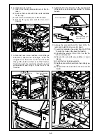
Main body instllation stay
TP screws (M4x18)
<Finisher accessory parts>
Installation plate
TP screws (M4x6)
Main body installation plate (lower)
Main body connectors
PU-108 connectors
Lever
Main body
PU-108
Upper view
Lower view
IV. Installation procedure for main body
[For Konica 7085/ 7075/ Force 75/ DP-75]
[PU-108+FS-108/108B/108BM and
PU-108+FS-111/211 installation procedure]
1. Turn the power to the main body OFF, then unplug
the power cord from the power outlet.
2. Install the main body installation stay on the upper
left side of the main body. (TP screw M4x18: 2
pcs. <Finisher accessory parts>)
Caution:
If the Finisher has been installed on the main body,
remove the main body installation plate (upper)
<Finisher accessory part> from the upper-left side
of the main body, then perform Step 2. ( TP screw
M4x18: 2 pcs.)
3. Remove the installation plate (1 screw) from the
main body installation plate (upper) <Finisher
accessory part>, then install it on the main body
installation stay. (1 screw)
4. Install the main body installation plate (lower)
<Finisher accessory part> on the lower left side of
the main body. (TP screw M4x6: 2 pcs. <Finisher
accessory parts>)
Caution:
If the Finisher has been installed on the main body,
use the main body installation plate (lower) as-is.
5. Connect the two PU-108 connectors to the
connectors on the rear paper-exit side of the main
body.
6. Install the PU-108+the Finisher on the main body.
(1) Lower the paper guide of the PU-108 (by
pushing up the lever).
(2) Fit the hooks of the main body installation stay
and main body installation plate (lower) into the
upper and lower holes on the PU-108, as
illustrated below.
Summary of Contents for 7075/FORCE 75
Page 1: ...FEBRUARY 2003 CSM 7075 F75 7085 F85 SERVICE MANUAL MODELS 7075 FORCE 75 7085 FORCE 85...
Page 2: ......
Page 3: ...7075 FORCE 75 7085 FORCE 85 SERVICE MANUAL FEBRUARY 2003...
Page 39: ...OUTLINE 1...
Page 40: ...Blank page...
Page 55: ...1 15 MAIN BODY 11 Paper Exit Drive Section FRONT Paper exit roller Paper exit motor M10...
Page 58: ...1 18 MAIN BODY 14 Web Drive Section FRONT Web drive motor M16 Cleaning web...
Page 59: ...UNIT EXPLANATION 2...
Page 60: ...Blank page...
Page 62: ...2 A 2 EXTERNAL SECTION Blank page...
Page 120: ...2 K 6 TRAY 3 PAPER FEED UNIT Blank page...
Page 126: ...2 L 6 BY PASS TRAY Blank page...
Page 130: ...2 M 4 VERTICAL PAPER CONVEYANCE SECTION Blank page...
Page 154: ...2 O 8 FIXING UNIT Blank page...
Page 165: ...DISASSEMBLY ASSEMBLY 3...
Page 216: ...3 H 4 TONER SUPPLY UNIT Blank page...
Page 224: ...3 I 8 CLEANING TONER RECYCLE UNIT Blank page...
Page 232: ...3 J 8 PAPER FEED UNITS OF TRAYS 1 AND 2 Blank page...
Page 240: ...3 K 8 TRAY 3 PAPER FEED UNIT Blank page...
Page 292: ...3 O 18 FIXING UNIT Blank page 3 O 16...
Page 293: ...MODELS 7075 FORCE 75 7085 FORCE 85 SERVICE SECTION FEBRUARY 2003...
Page 294: ......
Page 315: ...ADJUSTMENT 1...
Page 316: ......
Page 343: ...1 19 25 ADJUSTMENT Blank page 1 19 2...
Page 372: ...1 44 25 ADJUSTMENT 1 ADJUSTMENT Blank page...
Page 458: ...1 114 OTHER ADJUSTMENT Blank page 1 112 2...
Page 497: ...ISW 2...
Page 498: ......
Page 511: ...SERVICE 3...
Page 512: ......
Page 514: ...Blank page...
Page 550: ...3 18 SERVICE Blank page...
Page 551: ...ELECTRICAL PARTS LIST WIRING DIAGRAMS 4...
Page 552: ......
Page 611: ...JAM ERROR CODE LIST 5...
Page 612: ......
Page 625: ...5 13 JAM CODE LIST Blank page 5 11 2...
Page 659: ...TIMING CHARTS 6...
Page 660: ......
Page 678: ...6 18 TIMING CHARTS Blank page...
Page 679: ...INSTALLATION INSTRUCTIONS 7...
Page 680: ......
Page 692: ...Blank page...
Page 704: ...Blank page...
Page 724: ...Blank page...
Page 730: ...Blank page...
Page 736: ...Blank page...
Page 758: ...Blank page...
Page 780: ...Blank page...
Page 832: ...Blank page...
Page 833: ...APPENDIX 7085 OVERALL WIRING DIAGRAM...
Page 834: ......


