1 - 121
OTHER ADJUSTMENT
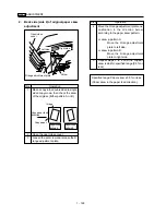
[10] RADF Paper Skew Adjustment
1.
Face side (side 1) of original paper skew
Note:
Always perform this adjustment after
completing the RADF skew adjustment.
(Refer to the previuos page.)
Step
Operation
1
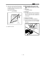
Make a copy in the single sided to single
sided copy mode, then check the skew
of the original. (Either pattern A or B)
2
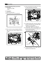
Open the open/close cover.
3
Loosen the retaining screw to release the
registration pulley bracket.
Step
Operation
4
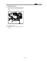
Move the registration pulley bracket one
calibration in the direction below
according to the paper skew pattern.
For skew in pattern A:
Move the registration pulley
bracket downwards (direction
down with original feed flow).
For skew in pattern B:
Move the registration pulley
bracket upwards (direction up
towards original feed flow).
Note:
Make sure that the registration
pulley shaft does not touch the
open/close cover spring holder
unit.
5
Repeat steps 2 to 4 until the original
skew is whithin specified range (0.5% or
less)
Screw
Registration pulley bracket
Open/close
cover
Upwards
Downwards
Copy paper feed
direction
Copy paper
Image
Paper skew
pattern A
Paper skew
pattern B
Registration
roller
Specified range: Paper skew ±0.5% or less
(Paper skew in the paper feed direction)
Summary of Contents for 7075/FORCE 75
Page 1: ...FEBRUARY 2003 CSM 7075 F75 7085 F85 SERVICE MANUAL MODELS 7075 FORCE 75 7085 FORCE 85...
Page 2: ......
Page 3: ...7075 FORCE 75 7085 FORCE 85 SERVICE MANUAL FEBRUARY 2003...
Page 39: ...OUTLINE 1...
Page 40: ...Blank page...
Page 55: ...1 15 MAIN BODY 11 Paper Exit Drive Section FRONT Paper exit roller Paper exit motor M10...
Page 58: ...1 18 MAIN BODY 14 Web Drive Section FRONT Web drive motor M16 Cleaning web...
Page 59: ...UNIT EXPLANATION 2...
Page 60: ...Blank page...
Page 62: ...2 A 2 EXTERNAL SECTION Blank page...
Page 120: ...2 K 6 TRAY 3 PAPER FEED UNIT Blank page...
Page 126: ...2 L 6 BY PASS TRAY Blank page...
Page 130: ...2 M 4 VERTICAL PAPER CONVEYANCE SECTION Blank page...
Page 154: ...2 O 8 FIXING UNIT Blank page...
Page 165: ...DISASSEMBLY ASSEMBLY 3...
Page 216: ...3 H 4 TONER SUPPLY UNIT Blank page...
Page 224: ...3 I 8 CLEANING TONER RECYCLE UNIT Blank page...
Page 232: ...3 J 8 PAPER FEED UNITS OF TRAYS 1 AND 2 Blank page...
Page 240: ...3 K 8 TRAY 3 PAPER FEED UNIT Blank page...
Page 292: ...3 O 18 FIXING UNIT Blank page 3 O 16...
Page 293: ...MODELS 7075 FORCE 75 7085 FORCE 85 SERVICE SECTION FEBRUARY 2003...
Page 294: ......
Page 315: ...ADJUSTMENT 1...
Page 316: ......
Page 343: ...1 19 25 ADJUSTMENT Blank page 1 19 2...
Page 372: ...1 44 25 ADJUSTMENT 1 ADJUSTMENT Blank page...
Page 458: ...1 114 OTHER ADJUSTMENT Blank page 1 112 2...
Page 497: ...ISW 2...
Page 498: ......
Page 511: ...SERVICE 3...
Page 512: ......
Page 514: ...Blank page...
Page 550: ...3 18 SERVICE Blank page...
Page 551: ...ELECTRICAL PARTS LIST WIRING DIAGRAMS 4...
Page 552: ......
Page 611: ...JAM ERROR CODE LIST 5...
Page 612: ......
Page 625: ...5 13 JAM CODE LIST Blank page 5 11 2...
Page 659: ...TIMING CHARTS 6...
Page 660: ......
Page 678: ...6 18 TIMING CHARTS Blank page...
Page 679: ...INSTALLATION INSTRUCTIONS 7...
Page 680: ......
Page 692: ...Blank page...
Page 704: ...Blank page...
Page 724: ...Blank page...
Page 730: ...Blank page...
Page 736: ...Blank page...
Page 758: ...Blank page...
Page 780: ...Blank page...
Page 832: ...Blank page...
Page 833: ...APPENDIX 7085 OVERALL WIRING DIAGRAM...
Page 834: ......


