E-2
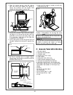
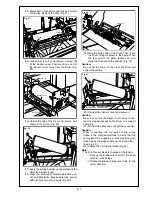
1. Place the wooden spacers under the Adjuster
feet. Then extend the Adjuster feet enough to
remove the cushions with the spanner (Not
attached to the accessory box) (Fig. 05).
2. Remove the cushions. Then wind up the Adjuster
feet again to let the machine descend onto the
pallet. Be sure to work on the above steps 1 and
2 in succession, respectively for the right side
and left side of the machine.
3. Fix the veneer with 2 nails at the right end face of
the pallet, setting its beveled portion upward (Fig.
06).
4. Set the 4 cushions and 4 wooden spacers
removed from the machine, below the veneer as
illustrated below. (Fig. 07).
5. Bring down the machine carefully on the floor by
two persons (Fig. 08).
Caution :
Precautions for moving the main
body
Confirm that the Adjuster feet are fully wound up
before moving the machine.
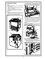
IV. Accessories Packed with the Main Body
1. Wooden spacers
2. Operation manual holder
3. Ventilation duct
4. Developer (For U.S.A only)
5. Cotton swabs
6. Setup report (For U.S.A only)
7. Unpacking and installation manual
8. Operation manual (Other than Europe)
9. Operation sheet (French) / (For Europe only)
10.Operation sheet (German) / (For Europe only)
11.Operation sheet (Italian) / (For Europe only)
12.Operation sheet (Spanish) / (For Europe only)
13.Nails
14.Veneer
15.Bind screws M3 x 6 : 2pcs.
16.Printer relay wiring / 1
17.Cable tie
18.Mounting clamp : 2pcs.
Cushions
Wooden spacer
Adjuster foot
Spanner
Fig. 05
Corrugated fiberboard
Nail: 2pcs
Veneer
Fig. 06
(A)
(D) or (E)
2 Spacers
Corrugated
fiberboard
Veneer
(A)
(D) or (E)
2 Spacers
Cushion rear (A)
Cushion front (D, E)
Cushion left (B, C)
Fig. 07
Fig. 08
Summary of Contents for 7075/FORCE 75
Page 1: ...FEBRUARY 2003 CSM 7075 F75 7085 F85 SERVICE MANUAL MODELS 7075 FORCE 75 7085 FORCE 85...
Page 2: ......
Page 3: ...7075 FORCE 75 7085 FORCE 85 SERVICE MANUAL FEBRUARY 2003...
Page 39: ...OUTLINE 1...
Page 40: ...Blank page...
Page 55: ...1 15 MAIN BODY 11 Paper Exit Drive Section FRONT Paper exit roller Paper exit motor M10...
Page 58: ...1 18 MAIN BODY 14 Web Drive Section FRONT Web drive motor M16 Cleaning web...
Page 59: ...UNIT EXPLANATION 2...
Page 60: ...Blank page...
Page 62: ...2 A 2 EXTERNAL SECTION Blank page...
Page 120: ...2 K 6 TRAY 3 PAPER FEED UNIT Blank page...
Page 126: ...2 L 6 BY PASS TRAY Blank page...
Page 130: ...2 M 4 VERTICAL PAPER CONVEYANCE SECTION Blank page...
Page 154: ...2 O 8 FIXING UNIT Blank page...
Page 165: ...DISASSEMBLY ASSEMBLY 3...
Page 216: ...3 H 4 TONER SUPPLY UNIT Blank page...
Page 224: ...3 I 8 CLEANING TONER RECYCLE UNIT Blank page...
Page 232: ...3 J 8 PAPER FEED UNITS OF TRAYS 1 AND 2 Blank page...
Page 240: ...3 K 8 TRAY 3 PAPER FEED UNIT Blank page...
Page 292: ...3 O 18 FIXING UNIT Blank page 3 O 16...
Page 293: ...MODELS 7075 FORCE 75 7085 FORCE 85 SERVICE SECTION FEBRUARY 2003...
Page 294: ......
Page 315: ...ADJUSTMENT 1...
Page 316: ......
Page 343: ...1 19 25 ADJUSTMENT Blank page 1 19 2...
Page 372: ...1 44 25 ADJUSTMENT 1 ADJUSTMENT Blank page...
Page 458: ...1 114 OTHER ADJUSTMENT Blank page 1 112 2...
Page 497: ...ISW 2...
Page 498: ......
Page 511: ...SERVICE 3...
Page 512: ......
Page 514: ...Blank page...
Page 550: ...3 18 SERVICE Blank page...
Page 551: ...ELECTRICAL PARTS LIST WIRING DIAGRAMS 4...
Page 552: ......
Page 611: ...JAM ERROR CODE LIST 5...
Page 612: ......
Page 625: ...5 13 JAM CODE LIST Blank page 5 11 2...
Page 659: ...TIMING CHARTS 6...
Page 660: ......
Page 678: ...6 18 TIMING CHARTS Blank page...
Page 679: ...INSTALLATION INSTRUCTIONS 7...
Page 680: ......
Page 692: ...Blank page...
Page 704: ...Blank page...
Page 724: ...Blank page...
Page 730: ...Blank page...
Page 736: ...Blank page...
Page 758: ...Blank page...
Page 780: ...Blank page...
Page 832: ...Blank page...
Page 833: ...APPENDIX 7085 OVERALL WIRING DIAGRAM...
Page 834: ......


