vi
SAFETY AND IMPORTANT WARNING ITEMS
[2] CHECKPOINTS WHEN PERFORMING ON-SITE SERVICE
Konica copiers are extensively tested before shipping, to ensure that all applicable safety standards are met, in order to
protect the customer and customer engineer (hereafter called the CE) from the risk of injury. However, in daily use, any
electrical equipment may be subject to parts wear and eventual failure. In order to maintain safety and reliability, the CE
must perform regular safety checks.
1.Power Supply
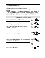
WARNING: Wall Outlet
• Check that mains voltage is as specified. Plug the power cord into the
dedicated wall outlet with a capacity greater than the maximum power
consumption.
If excessive current flows in the wall outlet, fire may result.
• If two or more power cords can be plugged into the wall outlet, the total load
must not exceed the rating of the wall outlet.
If excessive current flows in the wall outlet, fire may result.
kw
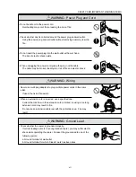
WARNING: Power Plug and Cord
• Make sure the power cord is plugged in the wall outlet securely.
Contact problems may lead to increased resistance, overheating, and
the risk of fire.
• Check whether the power cord is damaged. Check whether the sheath is
damaged.
If the power plug, cord, or sheath is damaged, replace with a new power
cord (with plugs on both ends) specified by Konica. Using the damaged
power cord may result in fire or electric shock.
• When using the power cord (inlet type) that came with this copier, be sure to
observe the following precautions:
a.Make sure the copier-side power plug is securely inserted in the socket on
the rear panel of the copier.
Secure the cord with a fixture properly.
b.If the power cord or sheath is damaged, replace with a new power cord
(with plugs on both ends) specified by Konica.
If the power cord (inlet type) is not connected to the copier securely, a
contact problem may lead to increased resistance, overheating, and risk of
fire.
• Check whether the power cord is not stepped on or pinched by a table and so
on.
Overheating may occur there, leading to a risk of fire.
Summary of Contents for 7075/FORCE 75
Page 1: ...FEBRUARY 2003 CSM 7075 F75 7085 F85 SERVICE MANUAL MODELS 7075 FORCE 75 7085 FORCE 85...
Page 2: ......
Page 3: ...7075 FORCE 75 7085 FORCE 85 SERVICE MANUAL FEBRUARY 2003...
Page 39: ...OUTLINE 1...
Page 40: ...Blank page...
Page 55: ...1 15 MAIN BODY 11 Paper Exit Drive Section FRONT Paper exit roller Paper exit motor M10...
Page 58: ...1 18 MAIN BODY 14 Web Drive Section FRONT Web drive motor M16 Cleaning web...
Page 59: ...UNIT EXPLANATION 2...
Page 60: ...Blank page...
Page 62: ...2 A 2 EXTERNAL SECTION Blank page...
Page 120: ...2 K 6 TRAY 3 PAPER FEED UNIT Blank page...
Page 126: ...2 L 6 BY PASS TRAY Blank page...
Page 130: ...2 M 4 VERTICAL PAPER CONVEYANCE SECTION Blank page...
Page 154: ...2 O 8 FIXING UNIT Blank page...
Page 165: ...DISASSEMBLY ASSEMBLY 3...
Page 216: ...3 H 4 TONER SUPPLY UNIT Blank page...
Page 224: ...3 I 8 CLEANING TONER RECYCLE UNIT Blank page...
Page 232: ...3 J 8 PAPER FEED UNITS OF TRAYS 1 AND 2 Blank page...
Page 240: ...3 K 8 TRAY 3 PAPER FEED UNIT Blank page...
Page 292: ...3 O 18 FIXING UNIT Blank page 3 O 16...
Page 293: ...MODELS 7075 FORCE 75 7085 FORCE 85 SERVICE SECTION FEBRUARY 2003...
Page 294: ......
Page 315: ...ADJUSTMENT 1...
Page 316: ......
Page 343: ...1 19 25 ADJUSTMENT Blank page 1 19 2...
Page 372: ...1 44 25 ADJUSTMENT 1 ADJUSTMENT Blank page...
Page 458: ...1 114 OTHER ADJUSTMENT Blank page 1 112 2...
Page 497: ...ISW 2...
Page 498: ......
Page 511: ...SERVICE 3...
Page 512: ......
Page 514: ...Blank page...
Page 550: ...3 18 SERVICE Blank page...
Page 551: ...ELECTRICAL PARTS LIST WIRING DIAGRAMS 4...
Page 552: ......
Page 611: ...JAM ERROR CODE LIST 5...
Page 612: ......
Page 625: ...5 13 JAM CODE LIST Blank page 5 11 2...
Page 659: ...TIMING CHARTS 6...
Page 660: ......
Page 678: ...6 18 TIMING CHARTS Blank page...
Page 679: ...INSTALLATION INSTRUCTIONS 7...
Page 680: ......
Page 692: ...Blank page...
Page 704: ...Blank page...
Page 724: ...Blank page...
Page 730: ...Blank page...
Page 736: ...Blank page...
Page 758: ...Blank page...
Page 780: ...Blank page...
Page 832: ...Blank page...
Page 833: ...APPENDIX 7085 OVERALL WIRING DIAGRAM...
Page 834: ......


