SERVICE PROCEDURE
MAINTENANCE
4-36
BLEEDING AIR FROM PPC CIRCUIT
4
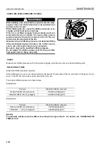
When removing piping of PPC circuit, or removing strainer, after assembling, bleed air from inside of the circuit as
follows:
1.
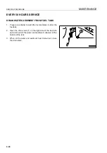
Put bucket control lever in TILT position and lift arm control lever in FLOAT position, and after cylinder reaches
stroke end, keep in that position for one minute.
2.
Put bucket control lever in DUMP position and lift arm control lever in RAISE position, and after cylinder
reaches stroke end, keep in that position for one minute.
For details, contact your Komatsu distributor.
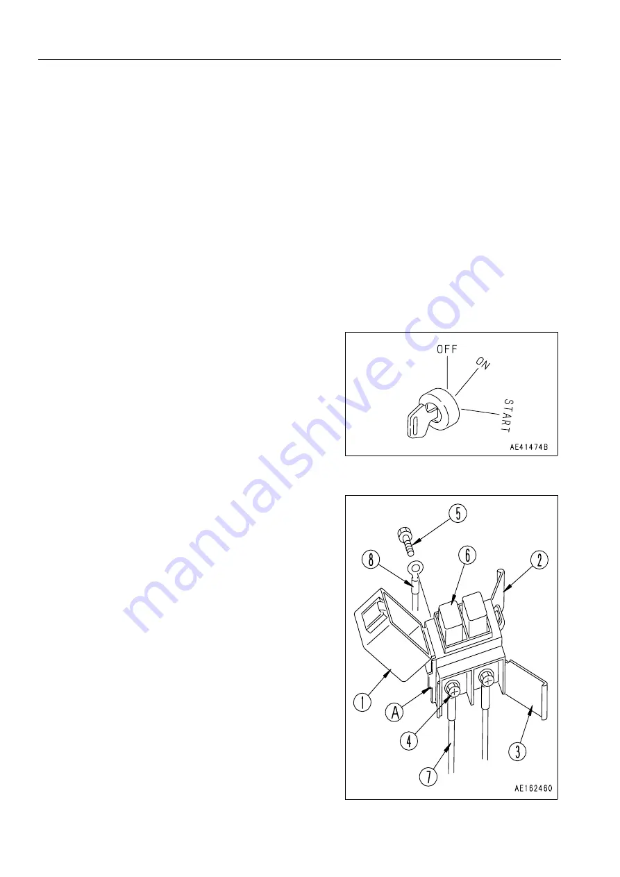
REPLACE SLOW BLOW FUSE
4
NOTICE
q
Always turn the power OFF when replacing the slow
blow fuse (turn the starting switch to the OFF posi-
tion).
q
Always replace the slow blow fuse with a fuse of the
same capacity.
1.
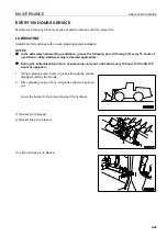
Turn the starting switch to the OFF position.
2.
Remove the slow blow fuse box from the chassis.
3.
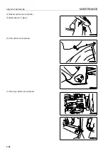
Open covers (1), (2), and (3) of the slow blow fuse box.
Covers (2) and (3) can be removed easily by using protru-
sion (A) on the body as a fulcrum and levering the catch of
the cover with a flat-headed screwdriver to release it.
4.
Loosen screws (4) and (5), and remove.
When screws (4) and (5) are removed, slow blow fuse (6)
will also come off together with electric wiring (7) and (8).
5.
Using screws (4) and (5), install a new slow blow fuse
together with electric wiring (7) and (8) to the slow blow
fuse box, then close covers (1), (2), and (3).
6.
Install the slow blow fuse box to the chassis.
Summary of Contents for WA800-3E0
Page 2: ......
Page 3: ...FOREWORD 11...
Page 27: ...SAFETY SAFETY LABELS 2 5 LOCATION OF SAFETY LABELS 2...
Page 66: ...GENERAL VIEW OPERATION 3 4...
Page 84: ...EXPLANATION OF COMPONENTS OPERATION 3 22 SWITCHES 3...
Page 224: ...TROUBLESHOOTING OPERATION 3 162...
Page 309: ...SPECIFICATIONS 15...
Page 330: ...HANDLING MACHINES EQUIPPED WITH VHMS ATTACHMENTS OPTIONS 6 20...
Page 331: ...INDEX 17...
Page 332: ...INDEX 7 2...
Page 335: ...COLOPHON 18...


