DETAILED CONTROLS AND GAUGES
OPERATION
3-32
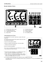
Function Switches
Function switches (7) consist of 6 switches (F1 to F6). The
function of each switch differs according to the content of each
screen.
When the monitor display shows the standard screen, the func-
tions are displayed as follows.
F3: Camera screen selector switch (if equipped)
F4: Service meter/time display selector switch
F5: Maintenance mode switch
F6: User mode switch
F1 and F2 are auxiliary switches for expanded functions.
For explanation of each switch, see “Handling Function
Switches (3-33)“.
Air Conditioner Switch
The air conditioner switches (8) consist of 9 switches.
For explanation of each switch, see “AIR CONDITIONER
CONTROLS (3-88)“.
Summary of Contents for PC450-8
Page 2: ......
Page 3: ...FOREWORD 11 ...
Page 66: ...SAFETY MAINTENANCE INFORMATION SAFETY 2 42 ...
Page 351: ...SPECIFICATIONS 15 ...
Page 355: ...SPECIFICATIONS SPECIFICATIONS 5 5 6 7m Boom PC450 8 ...
Page 356: ...SPECIFICATIONS SPECIFICATIONS 5 6 6 7m Boom PC450LC 8 ...
Page 357: ...SPECIFICATIONS SPECIFICATIONS 5 7 6 7m Boom PC450LCHD 8 ...
Page 359: ...SPECIFICATIONS SPECIFICATIONS 5 9 7 0m Boom PC450 8 ...
Page 360: ...SPECIFICATIONS SPECIFICATIONS 5 10 7 0m Boom PC450LC 8 ...
Page 410: ...SUPER LONG FRONT BOOM AND ARM ATTACHMENTS ANDD OPTIONS 6 50 ...
Page 436: ...OPERATION HIGH REACH DEMOLITION EQUIPMENT 27M 7 26 3 Extend arm cylinder Arm cylinder ...
Page 469: ...INDEX 18 ...
Page 470: ...INDEX 8 2 ...
Page 473: ...COLOPHON 18 ...

