HIGH REACH DEMOLITION EQUIPMENT 27M
OPERATION
7-29
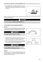
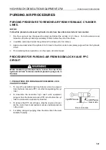
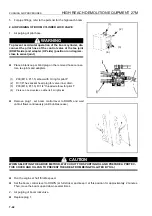
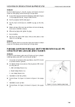
Adjustment of boom angle warning sensor.
1.
Loosen bolt (A) and adjust so that clearance between the
proximity switch and plate (1) is 5 - 8 mm.
2.
Raise the boom to the maximum height, then gradually lower
it and stop the boom at the position where the indicator of the
inclination gauge is on line (P) between the green range and
red range.
3.
Loosen bolt (B) and move plate (2) to the left or right to fix
dimension (L) so that the buzzer sounds at this position.
REMARK
Set clearance so that there is no contact even when the boom is
moved.
WARNING
This adjustment should only be performed by Komatsu Certi-
fied Mechanics. Failure to adjust properly may result in an
unsafe operating condition.
Boom
Proximity
switch
Proximity
switch
Clearance
Red range
Green range
Plate
Plate
Summary of Contents for PC450-8
Page 2: ......
Page 3: ...FOREWORD 11 ...
Page 66: ...SAFETY MAINTENANCE INFORMATION SAFETY 2 42 ...
Page 351: ...SPECIFICATIONS 15 ...
Page 355: ...SPECIFICATIONS SPECIFICATIONS 5 5 6 7m Boom PC450 8 ...
Page 356: ...SPECIFICATIONS SPECIFICATIONS 5 6 6 7m Boom PC450LC 8 ...
Page 357: ...SPECIFICATIONS SPECIFICATIONS 5 7 6 7m Boom PC450LCHD 8 ...
Page 359: ...SPECIFICATIONS SPECIFICATIONS 5 9 7 0m Boom PC450 8 ...
Page 360: ...SPECIFICATIONS SPECIFICATIONS 5 10 7 0m Boom PC450LC 8 ...
Page 410: ...SUPER LONG FRONT BOOM AND ARM ATTACHMENTS ANDD OPTIONS 6 50 ...
Page 436: ...OPERATION HIGH REACH DEMOLITION EQUIPMENT 27M 7 26 3 Extend arm cylinder Arm cylinder ...
Page 469: ...INDEX 18 ...
Page 470: ...INDEX 8 2 ...
Page 473: ...COLOPHON 18 ...

