


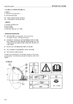

MAINTENANCE
MAINTENANCE PROCEDURE
4-79
4.
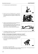
Stop the engine.
5.
Turn the starting switch to the ON position (B).
6.
Set lock lever to FREE position (F), then operate the work
equipment control levers and the attachment control pedal
(if equipped) fully to the front, rear, left, and right to release
the pressure in the control circuit.
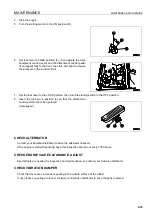
7.
Set the lock lever to the LOCK position, then turn the starting switch to the OFF position.
8.
Insert the lock pin in position (a) so that the attachment
control pedal cannot be operated.
(If equipped)
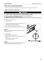
CHECK ALTERNATOR
4
Contact your Komatsu distributor to have the alternator checked.
If the engine is started frequently, have this inspection carried out every 1000 hours.
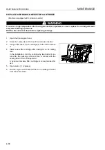
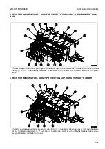
CHECK ENGINE VALVE CLEARANCE, ADJUST
4
Special tools are needed for inspection and maintenance, so contact your Komatsu distributor.
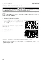
CHECK VIBRATION DAMPER
4
Check that there are no cracks or peeling in the outside surface of the rubber.
If any cracks or peeling are found, contact your Komatsu distributor to have the parts replaced.
Summary of Contents for PC450-8
Page 2: ......
Page 3: ...FOREWORD 11 ...
Page 66: ...SAFETY MAINTENANCE INFORMATION SAFETY 2 42 ...
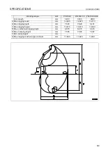
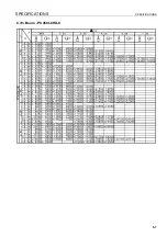
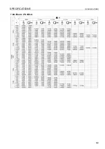
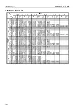
Page 351: ...SPECIFICATIONS 15 ...
Page 355: ...SPECIFICATIONS SPECIFICATIONS 5 5 6 7m Boom PC450 8 ...
Page 356: ...SPECIFICATIONS SPECIFICATIONS 5 6 6 7m Boom PC450LC 8 ...
Page 357: ...SPECIFICATIONS SPECIFICATIONS 5 7 6 7m Boom PC450LCHD 8 ...
Page 359: ...SPECIFICATIONS SPECIFICATIONS 5 9 7 0m Boom PC450 8 ...
Page 360: ...SPECIFICATIONS SPECIFICATIONS 5 10 7 0m Boom PC450LC 8 ...
Page 410: ...SUPER LONG FRONT BOOM AND ARM ATTACHMENTS ANDD OPTIONS 6 50 ...
Page 436: ...OPERATION HIGH REACH DEMOLITION EQUIPMENT 27M 7 26 3 Extend arm cylinder Arm cylinder ...
Page 469: ...INDEX 18 ...
Page 470: ...INDEX 8 2 ...
Page 473: ...COLOPHON 18 ...