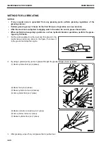
7.
After replacing the filter cartridge, open the engine hood
and fill with engine oil through oil filler port (F) to the mid-
point between H and L marks on dipstick (G).
8.
Run the engine at idle for a time, then stop the engine and
check that the oil level is between H and L marks on the
dipstick. For details, see “METHOD FOR CHECKING OIL
LEVEL IN ENGINE OIL PAN, ADDING OIL”.
9.
Install undercover.
REMARK
When the ambient temperature is low, water or emulsified matter may stick to the dipstick, oil filler cap, etc. or
the drained oil may be milky white because of water vapor in the blowby gas. However, if the coolant level is
normal, it is not a problem.
There is no problem even if the emulsified matter cannot be removed completely after changing oil.
METHOD FOR REPLACING FUEL PREFILTER CARTRIDGE
k
k
WARNING
• After the engine stops, all parts are still very hot, so do not replace the filter immediately. Wait until
all of parts cool down before starting the work.
• High pressure is generated inside the engine fuel piping system when the engine is running.
When replacing the filter, wait for at least 30 seconds after stopping the engine to let the internal
pressure go down before replacing the filter.
• Do not bring any open flame close.
NOTICE
• Komatsu genuine fuel filter cartridges use a special filter that has highly efficient filtering ability.
When replacing parts, Komatsu recommends using Komatsu genuine parts.
• The common rail fuel injection system used on this machine consists of more precise parts than
those in the conventional injection pump and nozzles. If any cartridge other than a Komatsu genu-
ine filter cartridge is used, dust or dirt may get in and cause problems with the injection system.
Never use a substitute.
• When performing inspection and maintenance of the fuel system, be careful not to let any dirt or
dust get in, more than ever before. If dust sticks to the fuel system, wash it off thoroughly with fuel.
Items to be prepared
• Container to catch drained oil
• Filter wrench
1.
Turn valve (1) at the bottom of the fuel tank to CLOSE po-
sition (S).
2.
Open the door on the right side of the machine.
MAINTENANCE PROCEDURE
MAINTENANCE
4-48
Summary of Contents for PC210-11
Page 2: ......
Page 24: ......
Page 74: ......
Page 352: ......
Page 431: ...SPECIFICATIONS 5 1 ...
Page 435: ...PC210LC 11 PC210NLC 11 SPECIFICATIONS SPECIFICATIONS 5 5 ...
Page 436: ...PC230NHD 11 SPECIFICATIONS SPECIFICATIONS 5 6 ...
Page 459: ...PC230NHD 11 2 Piece Boom ATTACHMENTS AND OPTIONS 2 PIECE BOOM 6 23 ...
Page 470: ... Not including tail swing SUPER LONG FRONT BOOM AND ARM ATTACHMENTS AND OPTIONS 6 34 ...
Page 505: ...REPLACEMENT PARTS 7 1 ...
Page 521: ......


