3.
Raise the lever of lock (D).
REMARK
If the reaction force of lock (D) is large, try it again by shift-
ing bracket (C).
4.
Insert connector (A).
Securely insert the connector until it clicks.
PROCEDURES FOR UNLOADING MACHINE
Perform unloading of the machine on a firm, level ground.
Maintain a safe distance from the road shoulder
1.
Apply the brake of the trailer securely.
2.
Set chocks (1) to the wheels to secure the trailer.
3.
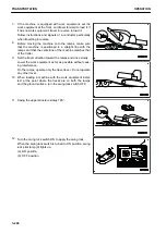
Set right and left ramps (2) parallel to each other and
equally spaced to the right and left of centre (3) of the trail-
er. Make angle of installation (4) a maximum of 15 °.
If the ramps bend a large amount under the weight of the
machine, put blocks under the ramps to prevent them from
bending.
4.
Remove the chains and wire ropes fastening the machine.
5.
Start the engine.
Warm the engine up fully in cold weather.
6.
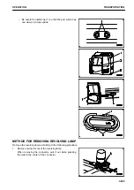
Operate the operating portion (g) of the lock lever to set it
securely to FREE position (F).
7.
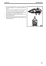
Push travel speed selector switch (5) to set the travel
speed to low (Lo lights up).
The travel speed (Lo, Mi, Hi) is displayed on travel speed
display (6).
TRANSPORTATION
OPERATION
3-258
Summary of Contents for PC210-11
Page 2: ......
Page 24: ......
Page 74: ......
Page 352: ......
Page 431: ...SPECIFICATIONS 5 1 ...
Page 435: ...PC210LC 11 PC210NLC 11 SPECIFICATIONS SPECIFICATIONS 5 5 ...
Page 436: ...PC230NHD 11 SPECIFICATIONS SPECIFICATIONS 5 6 ...
Page 459: ...PC230NHD 11 2 Piece Boom ATTACHMENTS AND OPTIONS 2 PIECE BOOM 6 23 ...
Page 470: ... Not including tail swing SUPER LONG FRONT BOOM AND ARM ATTACHMENTS AND OPTIONS 6 34 ...
Page 505: ...REPLACEMENT PARTS 7 1 ...
Page 521: ......


