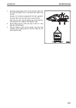
METHOD FOR LIFTING MACHINE
k
k
WARNING
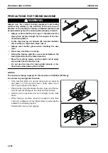
• The person using the crane to perform lifting operations must be a qualified crane operator.
• Never perform lifting operation if any person is on the machine being lifted.
• Always use a wire rope that has ample strength for the weight of the machine being lifted.
• When lifting, keep the machine horizontal.
• When performing lifting operations, set the lock lever to LOCK position to prevent the machine from
moving unexpectedly.
• Never enter the area under or around a lifted machine.
Never try to lift the machine in any other posture or by using any other lifting equipment than those giv-
en in the following procedures.
There is a danger of the machine losing its balance.
NOTICE
This method of lifting applies to the standard specification machine.
The method of lifting differs depending on the attachments and options installed.
For details of the procedure for machines other than the standard specification machine, consult your
Komatsu distributor.
For the weight, see “SPECIFICATIONS (5-1)”.
When lifting the machine, perform the operation on flat ground as follows.
1.
Start the engine.
2.
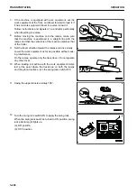
Swing the upper structure so that the work equipment is on
the sprocket (1) side.
3.
Extend the bucket cylinder and arm cylinder fully, then low-
er the work equipment to the ground using the boom cylin-
der as shown in the figure.
4.
Set the lock lever securely to LOCK position (L).
5.
Stop the engine.
6.
Check that there is nothing around the operator's seat, and
then get off the machine.
Close the cab door and front window securely.
TRANSPORTATION
OPERATION
3-260
Summary of Contents for PC210-11
Page 2: ......
Page 24: ......
Page 74: ......
Page 352: ......
Page 431: ...SPECIFICATIONS 5 1 ...
Page 435: ...PC210LC 11 PC210NLC 11 SPECIFICATIONS SPECIFICATIONS 5 5 ...
Page 436: ...PC230NHD 11 SPECIFICATIONS SPECIFICATIONS 5 6 ...
Page 459: ...PC230NHD 11 2 Piece Boom ATTACHMENTS AND OPTIONS 2 PIECE BOOM 6 23 ...
Page 470: ... Not including tail swing SUPER LONG FRONT BOOM AND ARM ATTACHMENTS AND OPTIONS 6 34 ...
Page 505: ...REPLACEMENT PARTS 7 1 ...
Page 521: ......

