background image

UPS306-01-00 PowerWAVE 9000 DPA User Manual Dated 01-06-2010

3-25

3:  Installation

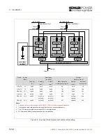
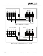
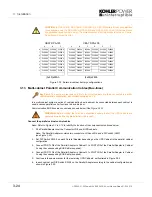
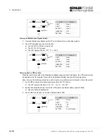
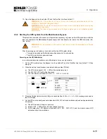
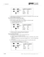
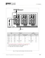
Figure 3.20   Connection of the Bus-lines when paralleling UPS-Cabinet Parallel Adaptors

Configuration DIP Switch SW1-9

DIP Switch SW1-9, located in every cabinet, is used to configure the position of the cabinet in a multi-cabinet
parallel chain. Using this switch you can define the cabinet’s position as:

• the 

first

 cabinet in the chain (e.g. 

cabinet 1

 in Figure 3.20).

• The 

middle

 cabinet in the chain (there may be more than one).

• the 

last

 cabinet in the chain (e.g. 

cabinet n

 in Figure 3.20).

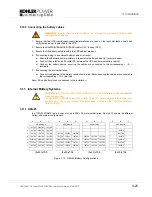
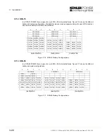
7.

Set DIP Switch SW1-9 on the Parallel Adaptor Board (PCB NW8141) of each cabinet according to the
table below:


First UPS

Middle UPS

Last UPS

Single UPS

SW 1a 1 

ON OFF ON ON 

SW 1b 2 

OFF OFF  ON  ON 

SW 1c 3 

ON OFF OFF ON 

SW 1d 4 

ON OFF ON ON 

SW 1e 5 

ON OFF ON ON 

SW 1f 6 

ON OFF ON ON 

SW 1g 7 

ON OFF ON ON 

SW 1h 8 

ON OFF ON ON

SW 1i 9

ON

OFF

ON

ON

U P S -C ab inet  1

U P S -C abinet 2

U P S -C abinet n-1

U P S -C abinet n

JD 6

JD5

Input

Mas ter-Slave

O utput

Mas ter-S lave

JD6

JD 5

Input

Mas ter-Slave

O u tput

Mas ter-Slave

P arallel Adaptor

Parallel Adapto r

S W 2-2

S W 2-2

JD 6

JD5

Input

Mas ter-Slave

O utput

Master-Slave

P arallel Adaptor

S W 2-2

JD 6

JD 5

Input

Mas ter-Slave

O utput

Mas ter-Slave

Parallel Adaptor

S W 2-2

Single

Unit

First

Unit

Middle 

Unit

Last

Unit

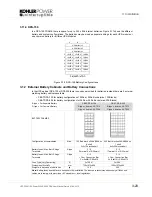
SW1

ON

OFF

OFF

ON

SW2

ON

ON

OFF

OFF

Summary of Contents for PW 9000DPA

Page 1: ...User Manual Pioneering solutions for total power protection Kohler PW 9000DPA ...

Page 2: ......

Page 3: ...UPS306 01 00 PowerWAVE 9000 DPA User Manual Dated 01 06 2010 Document Control ISSUE DATE REVISION SUMMARY 1 0 01 06 10 Initial issue ...

Page 4: ...nd easy to understand manual and will therefore assume no responsibility nor liability for direct indirect or accidental personal or material damage due to any misinterpretation of or accidental mistakes in this manual 2010 Kohler Uninterruptible Power This manual may not be copied nor reproduced without written permission of Kohler Uninterruptible Power ...

Page 5: ...ent FBM 2 5 2 4 4 Decentralized Parallel Architecture DPA 2 5 2 5 Warranty 2 6 2 6 Extended Warranty 2 6 2 7 Additional Service Maintenance Support 2 6 3 Installation 3 1 Introduction 3 1 3 2 Receipt of the UPS 3 1 3 2 1 Site transportation 3 1 3 3 Unpacking 3 2 3 3 1 Nameplate 3 2 3 4 Batteries 3 2 3 5 Storage 3 3 3 5 1 UPS 3 3 3 5 2 Battery 3 3 3 6 Positioning 3 3 3 6 1 Planning the installation...

Page 6: ... of the LCD 4 3 4 3 1 Status screens 4 3 4 3 2 Main menu screen 4 4 4 3 3 Event log menu screen 4 4 4 3 4 Measurements menu screen 4 4 4 3 5 Commands menu screen 4 5 4 3 6 UPS Data menu screen 4 5 4 3 7 Set up User menu screen 4 6 4 3 8 Set Up Service menu screen 4 6 4 4 Operating Modes 4 7 4 4 1 On Line Inverter mode 4 7 4 4 2 OFF Line also known as ECO or Bypass mode 4 7 4 4 3 Maintenance Bypass...

Page 7: ... and Alarms 6 2 6 4 Contacting Service 6 2 7 Options 7 1 Introduction 7 1 7 2 Remote Emergency Stop Facilities 7 1 7 3 Generator ON Facilities 7 2 7 4 WAVEMON Shutdown and Management Software 7 2 7 4 1 Why is UPS Management important 7 2 7 4 2 Wavemon Shutdown and Monitoring Software 7 3 7 5 SNMP CARD ADAPTER For Network Management Remote Monitoring 7 4 8 Specifications 8 1 Mechanical Characterist...

Page 8: ...iv UPS306 01 00 PowerWAVE 9000 DPA User Manual Dated 01 06 2010 ...

Page 9: ...structions and hazard warnings contained in this manual are read and fully understood WARNING High leakage current Ensure that the UPS has been correctly earthed before you connect the mains power supply WARNING This UPS must not be started up or put into use without having first been commissioned by a fully trained engineer authorised by the manufacturer WARNING All servicing must be performed by...

Page 10: ...1 Safety 1 2 UPS306 01 00 PowerWAVE 9000 DPA User Manual Dated 01 06 2010 ...

Page 11: ...ng cabinets which are purpose designed to contain up to one three or five modules Two cabinet ranges are available as standard the MD cabinet range is designed for use with 10kVA 25kVA modules see Figure 2 2 whereas MX cabinets are used with modules from 30kVA to 45kVA see Figure 2 3 Cabinets designed for three or fewer modules also contain the UPS batteries however an additional external battery ...

Page 12: ...r output In a capacity system opening this isolator this will cause the load to transfer to the unprotected bypass supply but in a redundant module system the load will continue to receive protected power until the number of off line modules exceeds the inbuilt system redundancy P o w e r WA V E D P A E N T E R O N O F F O N O F F R E S E T A L A R M L I N E 2 B Y P A S S L I N E 1 I N V E R T E R...

Page 13: ...mensions WxHxD mm 550x1650x780 550x1975x780 550x1975x780 Weight of Empty Frame kg 200 220 160 Weight of Frame with modules and no batteries kg 224 233 with 1 Module 292 319 with 3 Modules 280 325 with 5 Modules Colours Front RAL 9007 black inlets Side walls Graffito grey PowerWAVE DPA Modules DPA 10 DPA 15 DPA 20 DPA 25 Output Apparent Power KVA 10 15 20 25 Output Active Power KW 8 12 16 20 Output...

Page 14: ... a more reliable total system operation and savings in generator and transformer sizing as winding losses are minimised It also means that traditional harmonic filters are no longer required PowerWAVE DPA MX Frames CLASSIC DPA 50 TRIPLE DPA 150 UPGRADE DPA 250 Capacity Max 1 module 30 45kVA 280 x 7 9Ah batteries 3 modules 30 45kVA 240x 7 9Ah batteries 5 modules 30 45kVA External batteries Max Powe...

Page 15: ...ction thanks to Advanced Battery Diagnosis ABD Algorithm User selectable battery tests Optional temperature compensated charging to enhance battery life 2 4 4 Decentralized Parallel Architecture DPA In a redundant parallel UPS system the UPS modules are linked together in parallel so that in the event that one module fails the others can automatically sustain the load supply A parallel redundancy ...

Page 16: ...the use of any of its products in direct patient care Kohler Uninterruptible Power will not knowingly sell its products for use in such applications unless it receives in writing assurances satisfactory to Kohler Uninterruptible Power that the risks of injury or damage have been minimized the customer assumes all such risks and the liability of Kohler Uninterruptible Power is adequately protected ...

Page 17: ...iceUPS sg kohler com www kohlerups sg Kohler Uninterruptible Power 7 Jurong Pier Singapore 619159 Tel 65 6264 6422 Name Job Title Company Address Post Code Tel Fax E mail Please contact me to discuss Extended Warranty options for my PowerWAVE 9000 DPA UPS Extended warranty options for my UPS System as below Manufacturer Model Nº Rating kVA Replacement Batteries Other please specify Fax to 65 6302 ...

Page 18: ...2 Description 2 8 UPS306 01 00 PowerWAVE 9000 DPA User Manual Dated 01 06 2010 ...

Page 19: ...ase observe the following precautions WARNING All the operations described in this section must be performed by authorised electricians or suitably qualified personnel Kohler Uninterruptible Power will take no responsibility for any personal or material damage caused by incorrect cabling or operations or activities which are not carried out in strict accordance with the instructions contained in t...

Page 20: ...ch is situated at the front internal door of the UPS Check that the details on the nameplate corresponds to the purchased material detailed on the delivery note 3 4 Batteries The standard batteries connected to the UPS are sealed maintenance free batteries which will be mounted either within the UPS cabinet or an external battery cabinet The battery will usually be connected when the UPS is commis...

Page 21: ...inimum clearance at the back of the cabinet 4 All parts of the UPS required for maintenance servicing and user operation are accessible from the front Reserve a minimum of 1000mm space at the front of the UPS cabinet 5 An ambient temperature of 20 C is recommended to achieve a long battery life The cooling air entering the UPS must not exceed 40 C 6 Avoid high ambient temperature moisture and humi...

Page 22: ...ly to the UPS bypass circuit see Figure 3 5 or it can be wired with a dual feed input whereby the UPS bypass circuit is connected to a dedicated bypass supply see Figure 3 6 These diagrams identify the UPS input output cabling requirements and provides information regarding fuse ratings cable ratings and cable sizing Figure 3 4 outlines of the power terminal connections withing the various UPS cab...

Page 23: ... earth PE connection for the bypass if used as Dual Feed input Load Out three phase 3L1 3L2 3L3 neutral 3N protective earth PE connection for the load output External Battery Plus Common N Minus protective earth PE connection for the external batteries Input neutral grounding Figure 3 2 Input neutral grounding Key Point Input neutral is required to operate the rectifier In TN S systems no 4 pole i...

Page 24: ...input distribution board to each UPS cabinet should be of equal length Similarly the UPS output cables to the output distribution board should be of equal length See Figure 3 3 Figure 3 3 Cable Lengths for Multi Cabinet Configurations assuming a 2 cable input UPS 1 UPS 2 UPS 3 UPS 4 UPS 1 UPS 2 UPS 3 UPS 4 Recommended cable configurations The cable configuration below is not recommended Bypass Fee...

Page 25: ...ntil the UPS is properly installed at its intended final location 3 8 3 Connecting the UPS input power cables 1 To protect personnel during the UPS installation ensure that the connections are performed under the following conditions a No mains voltage is present b Loads are shut down and disconnected c The UPS is shut down and voltage free d The UPS Maintenance Bypass Isolator IA1 is OFF 2 Gain i...

Page 26: ...manufacturer 3 Do not operate the UPS if there is water or moisture present 4 When carrying out any work on the UPS output power cables you must ensure that the UPS supplies are isolated at the supply distribution panel and where possible locked out Warning notices should be posted where applicable to prevent inadvertent operation of the input supply isolators 3 9 2 Preparation for the output cabl...

Page 27: ...Gain internal access to the UPS and remove the UPS terminal cover if fitted 3 Connect the protective earth cable from the Load Distribution Board to the output protective earth PE terminals as shown in Figure 3 4 4 Connect the UPS output supply cables to terminals 3L1 3L2 3L3 and 3N on the UPS main terminal block Ensure correct clockwise phase rotation 5 Secure the cables to the fixing rail locate...

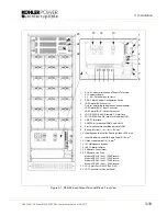
Page 28: ...0 95mm2 T PE 50mm2 T DPA 50 4 x 16 25mm2 T 5 x 16 25mm2 T 5 x 16 25mm2 T DPA 150 3 x M10 B PE 1xM10 B 4 x M10 B PE 1xM10 B 4 x M10 B PE 1xM10 B DPA 250 3 x M12 B PE 1xM12 B 4 x M12 B PE 1xM12 B 4 x M12 B PE 1xM12 B T signifies Terminals B signifies Bar See Figure 3 4 Fuse and Cable recommendations to IEC 60950 1 2001 or locally recoginsed standards The fuse and cable rating details in the above ta...

Page 29: ...ble recommendations to IEC 60950 1 2001 or locally recoginsed standards 2 The fuse and cable rating details in the above tables are a recommendation only 3 The UPS must be installed to prescribed IEC or local regulations 4 DC Cables and Battery fuses are bespoke to the installation FRAME Power kVA Single Input 3 x 400V Output 3x400V 0 8 pf Fuse A A Cable A mm2 Max Input with batt charging A Cable ...

Page 30: ...to IEC 60950 1 2001 or locally recoginsed standards 2 The fuse and cable rating details in the above tables are a recommendation only 3 The UPS must be installed to prescribed IEC or local regulations 4 DC Cables and Battery fuses are bespoke to the installation Frame Power kVA Dual Input 3 x 400V Output 3x400V 0 8 pf Fuse B C A Cable B mm2 Cable C mm2 Max Input with battery charging A Cable D mm2...

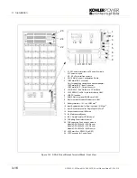
Page 31: ...5 JD12 RS232 Sub D9 male for Multidrop ONLY 6 USB PC Interface 7 SNMP Slot for optional SNMP card ONLY 8 Slot for optional Modem Ethernet card ONLY 9 Battery terminal N for 16 25 mm2 10 Input Bypass terminal for Dual Input feed 10 16 mm2 11 Input Rectifier terminal for Single feed 10 16 mm2 12 Output Load terminal 10 16 mm2 13 IA1 Maintenance Bypass 14 IA2 1 Parallel Isolator 15 F4 Battery Fuse Ho...

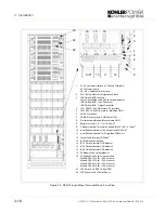
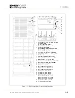
Page 32: ...ard ONLY 8 Slot for optional Modem Ethernet card ONLY 9 Battery terminal N for 16 25 mm2 9 3 Battery terminal for common battery for M6 PE 1x 16mm2 10 Input Bypass terminal for Dual Input feed 35 50mm2 11 Input Rectifier terminal for Single feed 35 50mm2 12 Output Load terminal 35 50mm2 13 IA1 Maintenance Bypass 14 IA2 1 Parallel Isolator UPS Module 1 15 IA2 2 Parallel Isolator UPS Module 2 16 IA2...

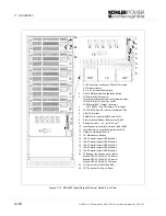
Page 33: ...ptional Modem Ethernet card ONLY 9 Battery terminal N for 16 25 mm2 9 3 Battery terminal for common battery for M10 PE 1x 50mm2 10 Input Bypass terminal for Dual Input feed 70 95mm2 11 Input Rectifier terminal for Single feed 70 95mm2 12 Output Load terminal 70 95mm2 13 IA1 Maintenance Bypass 14 IA2 1 Parallel Isolator UPS Module 1 15 IA2 2 Parallel Isolator UPS Module 2 16 IA2 3 Parallel Isolator...

Page 34: ...5 JD12 RS232 Sub D9 male for Multidrop ONLY 6 USB PC Interface 7 SNMP Slot for optional SNMP card ONLY 8 Slot for optional Modem Ethernet card ONLY 9 Battery terminal N for 16 25 mm2 10 Input Bypass terminal for Dual Input feed 16 25mm2 11 Input Rectifier terminal for Single feed 16 25mm2 12 Output Load terminal 16 25mm2 13 IA1 Maintenance Bypass 14 IA2 1 Parallel Isolator UPS Module 1 19 F4 Batte...

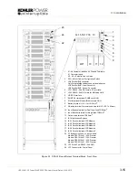
Page 35: ...or optional SNMP card ONLY 8 Slot for optional Modem Ethernet card ONLY 9 Battery terminal N for 16 25 mm2 10 Input Bypass terminal for Dual Input feed 3xM10 11 Input Rectifier terminal for Single feed 4xM10 12 Output Load terminal 4xM10 13 IA1 Maintenance Bypass 14 IA2 1 Parallel Isolator UPS Module 1 15 IA2 2 Parallel Isolator UPS Module 2 16 IA2 3 Parallel Isolator UPS Module 3 19 F4 Battery Fu...

Page 36: ...7 SNMP Slot for optional SNMP card ONLY 8 Slot for optional Modem Ethernet card ONLY 9 Battery terminal N for 16 25 mm2 10 Input Bypass terminal for Dual Input feed 3xM10 11 Input Rectifier terminal for Single feed 4xM10 12 Output Load terminal 4xM10 13 IA1 Maintenance Bypass 14 IA2 1 Parallel Isolator UPS Module 1 15 IA2 2 Parallel Isolator UPS Module 2 16 IA2 3 Parallel Isolator UPS Module 3 17 ...

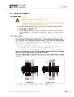
Page 37: ...idual battery where each module is connected to individual battery string These configurations are depicted in Figure 3 13 which shows the alternative connections for internal batteries in a 3 module cabinet Figure 3 14 shows an example of the alternative connections when using an external battery cabinet shown connected to a 5 module UPS cabinet The available battery configurations within the sta...

Page 38: ...fuse for UPS5 2 2 N 2 UPS3 N UPS2 N UPS1 N UPS3 UPS2 UPS1 UPS5 UPS4 UPS5 N UPS4 N UPS5 UPS4 For reasons of clarity the wiring for modules 1 3 5 only is shown in detail PE 1 1 N 1 3 3 N 3 4 4 N 4 5 5 N 5 PE TO UPS Modules EXTERNAL BATTERY CABINET UPS CABINET UPS CABINET UPS3 UPS2 UPS1 Battery fuse for UPS1 Battery fuse for UPS2 Battery fuse for UPS3 Battery fuse for UPS4 Battery fuse for UPS5 2 2 N...

Page 39: ... to the installation 3 11 Internal Battery Systems 3 11 1 DPA 25 In a DPA 25 FRAME there is space for up to 200 x 9Ah internal batteries Figure 3 15 shows the different battery and system configurations Figure 3 15 DPA 25 Battery Configurations WARNING This procedure must be carried out by or under the supervision of the system commissioning engineer CAUTION In DPA 10kVA DPA 15kVA DPA 20kVA 30 50 ...

Page 40: ...odule 1 UPS Module 1 6 10x7Ah 2x5x7Ah 10x7Ah 5 2x5x7Ah 2x5x7Ah 2x5x7Ah 10x7Ah 10x7Ah 10x7Ah 4 10x7Ah 2x5x7Ah 10x7Ah 10x7Ah 10x7Ah 10x7Ah 10x7Ah 10x7Ah 10x7Ah 3 10x7Ah 10x7Ah 10x7Ah 2x5x7Ah 2x5x7Ah 2x5x7Ah 10x7Ah 10x7Ah 10x7Ah 2 2x5x7Ah 2x5x7Ah 2x5x7Ah 10x7Ah 10x7Ah 10x7Ah 10x7Ah 10x7Ah 10x7Ah 1 10x7Ah 10x7Ah 10x7Ah 10x7Ah 10x7Ah 10x7Ah 10x7Ah 10x7Ah 10x7Ah 3x 2x30 x7Ah 3x50 x7Ah 3x40 x7Ah A B C D ...

Page 41: ...7Ah 5 10x7Ah 10x7Ah 10x7Ah 4 10x7Ah 10x7Ah 10x7Ah 3 10x7Ah 10x7Ah 10x7Ah 2 10x7Ah 10x7Ah 10x7Ah 1 10x7Ah 10x7Ah 10x7Ah 3x 2x40 x7Ah S type For Separate Battery C type For Common Battery CBAT DPA 120 S type item no 00 7912 C type item no 00 7964 CBAT DPA 200 S type item no 00 7913 C type item no 00 7965 BATTERY FRAMES Configuration accommodates Max 120 Batt block x 24Ah 28Ah on 8 shelf 3x5 15 block...

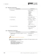
Page 42: ...nue in the same manner for the remaining UPS Cabinets as illustrated in Figure 3 20 6 In each cabinet set DIP Switch SW2 2 on the Parallel Adapter according to the cabinet configuration as shown in Figure 3 20 CAUTION In DPA 10kVA DPA 15kVA DPA 20kVA 30 50 12V battery blocks are permitted even numbers only In DPA 25kVA DPA 30kVA and DPA 50kVA 40 50 12V battery blocks are permitted even numbers onl...

Page 43: ...7 Set DIP Switch SW1 9 on the Parallel Adaptor Board PCB NW8141 of each cabinet according to the table below First UPS Middle UPS Last UPS Single UPS SW 1a 1 ON OFF ON ON SW 1b 2 OFF OFF ON ON SW 1c 3 ON OFF OFF ON SW 1d 4 ON OFF ON ON SW 1e 5 ON OFF ON ON SW 1f 6 ON OFF ON ON SW 1g 7 ON OFF ON ON SW 1h 8 ON OFF ON ON SW 1i 9 ON OFF ON ON UPS Cabinet 1 UPS Cabinet 2 UPS Cabinet n 1 UPS Cabinet n J...

Page 44: ... on the Interface Board when fitted to a Slave cabinet The Output ports X3 6 X3 10 The Output ports X4 1 X4 10 Means Alarm Module 1 2 3 4 5 All other input or output ports on the Slave boards are not activated Note Figure 3 21 shows the interface Board fitted to the DPA 75 cabinet For details of the other cabinets refer to Figures 3 7 to 3 12 to identify the location of the components mentioned be...

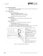
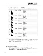
Page 45: ...tacts All the Input and Output interfaces are connected to Phoenix terminals cable 0 5 mm2 Input Interfaces Terminal block X1 Connection of Remote Shut down facilities Generator Operation Customers specials see Section 9 chapter 1 2 OPTIONS Figure 3 23 Dry Port X1 Connections Term Contact Signal Display Function X1 1 3 3Vdc GND Remote Shut down Do not remove the factory mounted bridge until extern...

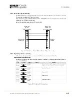
Page 46: ...l The connector JD12 is a standard D Type 9 pin male 3 14 6 USB 2 Computer Interface The Computer Interface USB 6 is in parallel with the intelligent RS 232 serial port JD11 When installed the USB Computer Interface and the optional WAVEMON software allows the computer to monitor the mains voltage and the UPS system status continuously Term Contact Signal Display Function X2 1 ALARM MAINS_OK Mains...

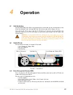
Page 47: ...ower Management Display PMD The 2 x 20 character LCD Power Management Display simplifies communication with the UPS and also provides UPS monitoring information The menu driven LCD enables the access to The Event register Monitoring the input and output voltage current frequency power Monitoring battery run time Perform commands such as UPS start up and shut down Load transfer from INVERTER to BYP...

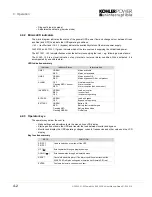
Page 48: ...nu driven LCD display Start up and shut down the UPS and transfer the load between inverter and bypass Monitor and display the UPS operating voltages currents frequencies and other values on the LCD display Key function summary Indicator Indicator Status Interpretation LINE 1 GREEN RED Mains available Mains not available LINE 2 GREEN RED Mains bypass OK Mains bypass not OK or not present ALARM OFF...

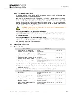
Page 49: ...ed simultaneously on one module and then action repeated on all remaining modules sequentially 4 3 Description of the LCD 4 3 1 Status screens Note The Unit number on the right hand side of the LCD indicates the cabinet number in a multi cabinet system together with the UPS module slot number within the cabinet The maximum number of Module units is 10 and the module slot number can vary from 1 to ...

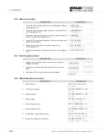
Page 50: ... 3 7 SET UP USER SET UP SERVICE 6 Password protected area for service engineer use only See paragraph 4 3 8 SET UP SERVICE DESCRIPTION LCD DISPLAY 1 Logging Control a log of the last 64 events is stored in the Power Management Display 01 05 10 08 14 38 56 LOAD TO INV 2 Every stored event is identified with a sequential number and time stamp 02 05 10 08 14 38 59 LOAD TO BYP 3 By pressing ENTER the ...

Page 51: ...parent Output Power all three phases APPARENT POWER KVA 00 00 00 00 00 00 14 Output Power all three phases OUTPUT POWER 00 00 00 00 00 00 15 Battery capacity BATT CAPACITY 00 00 DESCRIPTION LCD DISPLAY 1 Transfer Load to inverter LOAD TO INVERTER LOAD TO BYPASS 2 Transfer Load to bypass LOAD TO BYPASS PERFORM BATT TEST 3 Battery Test PERFORM BATT TEST DESCRIPTION LCD DISPLAY 1 These general UPS Da...

Page 52: ...isation window 2 4 DESCRIPTION LCD DISPLAY 1 Set up language SET LANGUAGE SET DATE AND TIME ENGLISH FRANCAIS DEUTCH DUTCH SPANISH POLISH PORTOGUESE 2 Set up Date and Time SET UP DATE TIME SET UP BATT TEST DD MM YY HH MM SS 3 Set up battery test SET UP BATT TEST SET UP GEN SET OPER DAY OF MONTH 1 31 HOUR OF DAY 0 23 REPETITIVE Y N 000 4 Set up operation with Gen Set SET UP GEN SET OPER BATT CHARGE ...

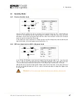
Page 53: ...ECO or Bypass mode In the Off Line ECO Bypass mode the load is supplied from the bypass mains LINE 2 and the static BYPASS In the event of a mains failure the load is automatically transferred to the inverter within 3 to 5 msec this is valid for single and parallel module systems The battery charger remains active in this mode Although this mode of operation offers greater efficiency than the On L...

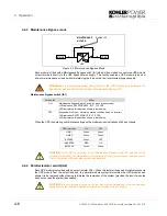
Page 54: ...ovided the loss of modules does not exceed the system redundancy WARNING In a multi module system ensure that ALL the UPS modules are operating in the Bypass mode before transferring the load to Maintenance Bypass IA1 Switch IA1 Effect ON Maintenance Bypass Switch Closed Load on bypass mains LCD indication MAINTENANCE BYP CLOSED LED Indicators will indicate as shown in table below OFF Bypass Switc...

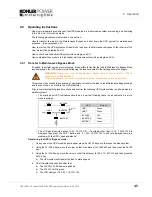
Page 55: ... commencing this procedure check and confirm the following UPS system status on all modules in a parallel system The mimic panel LED indications should be as per the following table on all cabinets in a multi module system The LCD panel should display LOAD PROTECTED If anything other than LOAD PROTECTED is displayed then press the RESET button and if LOAD PROTECTED is still not displayed there is ...

Page 56: ...y out the following procedure on each module in a parallel system to totally shut down the system 7 On the UPS control panel simultaneously press both ON OFF buttons a The LCD panel will indicate LOAD OFF SUPPLY FAILURE 8 Identify the associated battery fuse for the UPS module in external battery cabinet if fitted a Open the battery fuses breaker 9 On the UPS module open the module s Parallel Isol...

Page 57: ...ll be permanent green b The BATTERY LED will be flashing green c The LCD display will indicate LOAD OFF SUPPLY FAILURE 3 Close the Parallel Isolator switch IA2 and check that the PARALLEL SW CLOSED message is shown on the LCD display 4 On the UPS mimic panel press and release both ON OFF buttons simultaneously and wait approximately 60 seconds a The UPS module will begin to power up a Initially LI...

Page 58: ...ol Panel of any one module in a parallel module system a Press the UP key once to access the menu system b Use the UP DOWN keys to move the cursor so that it is adjacent to COMMANDS and then press the ENTER key c Use the UP DOWN keys move the cursor so that it is adjacent to LOAD TO INVERTER and then press the ENTER key 10 The UPS system will transfer the load to Inverter on all modules in a paral...

Page 59: ...FF SUPPLY FAILURE 4 Identify the associated battery cabinet rack for the UPS module a Open the battery fuses breaker on the battery cabinet rack 5 Open the module s Parallel Isolator switch IA2 6 Open the Bypass Line fuse holder F2 and the Rectifier Line fuse holder F1 7 Open the UPS Input and Bypass supply fused isolators or breakers in the building power distribution panel 8 The UPS is now volta...

Page 60: ...upply and Bypass supply fused isolators F1 F2 and the Parallel Isolator IA2 2 Close the UPS input supply isolator at the LV switchboard a The LINE 1 indicator will illuminate green b The LCD display will indicate LOAD OFF SUPPLY FAILURE If necessary press the RESET button to obtain this display 3 Identify the associated battery cabinet rack for the UPS module and close the fused battery isolators ...

Page 61: ...00 DPA consists of only one single UPS Module then perform the following steps to extract the module 1 Transfer the load to the Maintenance Bypass see paragraph 4 5 1 a The load is now directly supplied by mains and is not protected 2 Simultaneously press the two ON OFF buttons on the UPS control panel a The LED display will give the following indications WARNING All the operations in this section...

Page 62: ...tment opening with an appropriate protection cover and secure with four screws 4 6 2 Refitting the UPS Module 1 Remove the UPS module compartment protection cover if fitted by unscrewing four screws on the front 2 Using two persons to lift the UPS module slide two thirds of the module into the UPS compartment make sure not to plug the UPS Module into the rear connector 3 Push UPS module firmly int...

Page 63: ...the rear connectors are disconnected DO NOT FULLY EXTRACT THE UNIT 8 After waiting two minutes fully withdraw the UPS Module from the cabinet by pulling it horizontally 9 If you are not intending to replace the UPS module immediately cover the UPS compartment opening with an appropriate protection cover and secure with four screws WARNING All the operations in this section must be performed by aut...

Page 64: ...cally be transferred to bypass Bypass Mode or ECO Mode and will continue to be supplied by the mains supply 4 8 1 Removing a Module 1 Verify that the load is on BYPASS and is supplied by the mains power Bypass Mode or Eco Mode on ALL UPS modules a In the majority of the events the LED indicators on Control Panel of the faulty module will show b Whereas the LED indicators on the Control Panels of t...

Page 65: ...y 11 If you are not intending to replace the UPS module immediately cover the UPS compartment opening with an appropriate protection cover and secure with four screws 4 8 2 Refitting a Module in a Capacity Multi Module System 1 Remove the UPS Module compartment protection cover if fitted by unscrewing four screws on the front 2 Using two persons to lift the UPS module slide two thirds of the modul...

Page 66: ...l Dated 01 06 2010 4 Tighten the four screws on the front of module to secure it to the UPS cabinet frame 5 Connect the control panel cable to connector JD7 6 Start the UPS module and transfer the load from Maintenance Bypass to On Line mode See paragraph 4 5 2 ...

Page 67: ... the commissioning field service engineer will attach a service record book to the front of the UPS which will be used to log the full service history of the UPS Preventative maintenance inspections involve working inside the UPS which contains hazardous AC and DC voltages During a preventative maintenance inspection the field service engineer will check Site environment conditions Integrity of el...

Page 68: ...ly of the operating mode Off line or On line and whether or not the load is connected The battery test procedure can be performed from the UPS front panel See paragraph 4 3 5 5 6 Battery Maintenance The battery maintenance shall be done by an authorized Kohler Uninterruptible Power Service Partner 5 7 Battery Disposal and Recycling Batteries contain dangerous substances that will harm the environm...

Page 69: ... identification and rectification information is given on the following pages 6 2 Menu Commands Event Log Measurements A detailed description of the Menu Commands Event Log and Measurements that can be operated and displayed on the LCD can be found in Section 4 Event Log Screen The full list of Alarms and Messages are shown in section 6 3 As you step through the event memory make a separate note o...

Page 70: ... short circuit at the output of UPS on load side Check all output connections and repair as required OVERLOAD Load exceeds the UPS rated power Identify which piece of equipment is causing the overload and remove it from the UPS Do not connect laser printers photocopiers electric heaters kettles etc to the UPS OVERTEMPERATURE UPS temperature has exceeded the allowed value Check the ambient temperat...

Page 71: ...t which opens to operate the emergency stop sequence The emergency stop port X1 1 and X1 2 is located at the bottom of the DPA Cabinet on the communication card with terminal blocks X1 X4 See Figure 3 7 for a location drawing In order to permit removal maintenance or testing of any remote emergency stop facility without disturbing the normal UPS operation it is recommended that a terminal block wi...

Page 72: ...tem administrators can be assured that their electricity supplies are monitored for power disruptions and depleted battery conditions Such conditions pose the greatest threat through power disturbance to valuable computer data by causing possible corruption or loss By installing UPS Mains monitoring software administrators are able to monitor the utility power from a central location allowing earl...

Page 73: ...ation When UPSServ detects voltage variations or a power failure it can execute various so called system event routines which for example may shutdown the server or send a warning to connected users These system event routines are a part of the UPS Management Software can be adjusted to suit the customer s demands The UPS management software includes the licence for using the UPS service on one se...

Page 74: ...s used to monitor any device in the network and can be used utilising the RCCMD send function for an automatic network wide shut down or informing connected users The shut down procedure can be initiate from the remaining time downtime or as countdown timer from the beginning of the alarm A shut down is therefore possible without extra input from the operator but fully software controlled For deta...

Page 75: ...NMP Adapter The Internal SNMP Card can also be inserted into an appropriate expansion slot in the PowerWAVE 9000 Modules or Cabinet This adapter communicates via the serial port of the UPS and makes a direct multiple server shut down possible without additional SNMP management software ...

Page 76: ...7 Options 7 6 UPS306 01 00 PowerWAVE 9000 DPA User Manual Dated 01 06 2010 ...

Page 77: ...80 550x1975x780 550x1975x780 Weight of Empty Cabinet kg 200 220 160 Weight of Cabinet with modules and no batteries kg 224 233 with 1 Module 292 319 with 3 Modules 280 325 with 5 Modules Colours Front RAL 9007 black inlets Side walls Graffito grey PowerWAVE DPA UPSModules DPA 10 DPA 15 DPA 20 DPA 25 Output Apparent Power KVA 10 15 20 25 Output Active Power KW 8 12 16 20 Output Power PF 1 KVA KW 8 ...

Page 78: ...0 Weight of Empty Cabinet kg 250 270 190 Weight of Cabinet with modules and no batteries kg 300 310 with 1 Module 420 450 with 3 Modules 440 490 with 5 Modules Colours Front RAL 9007 black inlets Sidewalls Graffito grey PowerWAVE DPA MODULES DPA 30 DPA 40 DPA 50 Output Apparent Power KVA 30 40 45 Output Active Power KW 24 32 40 Output Power PF 1 KVA KW 24 24 32 32 40 40 Number of 12V Battery Block...

Page 79: ...ower and charged battery per Module output CosΦ 1 0 kW 8 5 12 8 17 0 21 3 25 4 33 9 42 9 Max Input Current with rated output power and charged battery per Module output CosΦ 1 0 A 12 3 18 5 24 7 30 8 36 8 49 1 62 1 Max Input Power with rated output power and discharged battery per Module output CosΦ 1 0 kW 9 3 14 0 18 6 23 3 27 8 37 1 46 9 Max Input Current with rated output power and discharged b...

Page 80: ...load 0 100 or 100 0 4 Output Voltage Distortion With Linear Load 2 With Non linear Load EN62040 3 2001 4 Output Frequency Hz 50 Hz or 60 Hz Output Frequency Tolerance Synchronized with mains 2 selectable or 4 Free running 0 1 Bypass operation At Nominal Input voltage of 3x400 V 15 or 190 V to 264 V ph N Permissible Unbalanced Load All 3 phases regulated independently 100 Phase Angle Tolerance With...

Page 81: ...humidity Max 95 non condensing Accessibility Totally front accessibility for service and maintenance no need for side top or rear access Positioning Min 20 cm rear space required for fan Input and Output Power Cabling From the bottom on the front Efficiency AC AC up to cosΦi 1 0 depending on Module power Load 100 75 50 25 DPA 30 50 94 5 94 5 94 93 DPA 10 25 94 94 93 5 91 Efficiency Linear Load at ...

Page 82: ... 208 226 550x1975x780 3 292 319 700x2150x895 232 259 550x1975x780 4 316 352 700x2150x895 256 292 550x1975x780 5 340 385 700x2150x895 280 325 550x1975x780 Fig UPS Modules Packed Weight Kg Packed Dimension mm Unpacked Weight Unpacked Dimension mm DPA 10 or 15 no Batt DPA 20 or 25 no Batt DPA 10 or 15 no Batt DPA 20 or 25 no Batt 8 4 DPA 50 1 360 367 370 880x1825x915 300 307 310 730x1650x800 8 5 DPA ...

Page 83: ...endations to IEC 60950 1 2001 or locally recoginsed standards 2 The fuse and cable rating details in the above tables are a recommendation only 3 The UPS must be installed to prescribed IEC or local regulations 4 DC Cables and Battery fuses are bespoke to the installation FRAME Power kVA Single Input 3 x 400V Output 3x400V 0 8 pf Fuse A A Cable A mm2 Max Input with batt charging A Cable D mm2 Nomi...

Page 84: ...50 1 2001 or locally recoginsed standards 2 The fuse and cable rating details in the above tables are a recommendation only 3 The UPS must be installed to prescribed IEC or local regulations 4 DC Cables and Battery fuses are bespoke to the installation Frame Power kVA Dual Input 3 x 400V Output 3x400V 0 8 pf Fuse B C A Cable B mm2 Cable C mm2 Max Input with battery charging A Cable D mm2 Nominal C...

Page 85: ...UPS306 01 00 PowerWAVE 9000 DPA User Manual Dated 01 06 2010 8 9 8 Specifications ...

Page 86: ...8 Specifications 8 10 UPS306 01 00 PowerWAVE 9000 DPA User Manual Dated 01 06 2010 ...

Reviews: