

UPS306-01-00 PowerWAVE 9000 DPA User Manual Dated 01-06-2010
4-11
4: Operation
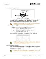
10. Open the Bypass Line fuse holder F2 and the Rectifier Line fuse holder F1.
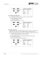
4.5.2 Starting the UPS system from the Maintenance Bypass
This procedure describes the sequence of operations necessary to power up the UPS module(s) whilst the
load is connected to the Maintenance Bypass supply, and then transfer the load to the UPS Inverter(s) (‘On-
Line’ mode).
Prior to powering-up the system, check and confirm the UPS system status:
• The load is supplied via the Maintenance Bypass switch (in all modules)
• The UPS module(s) are powered down
Powering up the UPS Module(s):
In a multi-module system perform each of the steps in turn on every module.
1.
On the UPS module close the Bypass Line fuse holder F2 and the Rectifier Line fuse holder F1 if they
are open.
2.
Close the battery fuses/breaker (in external battery cabinet if fitted).
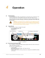
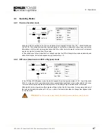
a)
The UPS mimic panel
LINE 1
LED will be permanent green.
b)
The
BATTERY
LED will be flashing green.
c)
The LCD display will indicate
LOAD OFF, SUPPLY FAILURE
.
3.
Close the Parallel Isolator switch (IA2) and check that the
PARALLEL SW CLOSED
message is shown on
the LCD display.
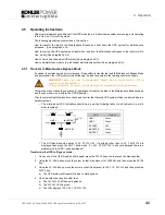
4.
On the UPS mimic panel press and release both
ON/OFF
buttons simultaneously and wait approximately
60 seconds.
a)
The UPS module will begin to power up.
a)
Initially
LINE 2
LED will be red, then change to green.
a)
At this stage the LCD display will indicate
LOAD NOT PROTECTED
and the module mimic LED
indications should be as follows:
WARNING:
The UPS cabinet is still live at its input and output power terminals due to the
activation of Maintenance Bypass circuit.
WARNING:
Allow 10 minutes for the internal DC capacitors to discharge before touching any
UPS internal components.
WARNING:
The load is now supplied from the bypass mains and is not protected against
power failure.
WARNING:
All the operations in this section must be performed by authorised and trained
personnel.
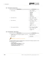
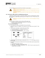
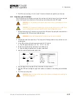
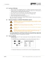
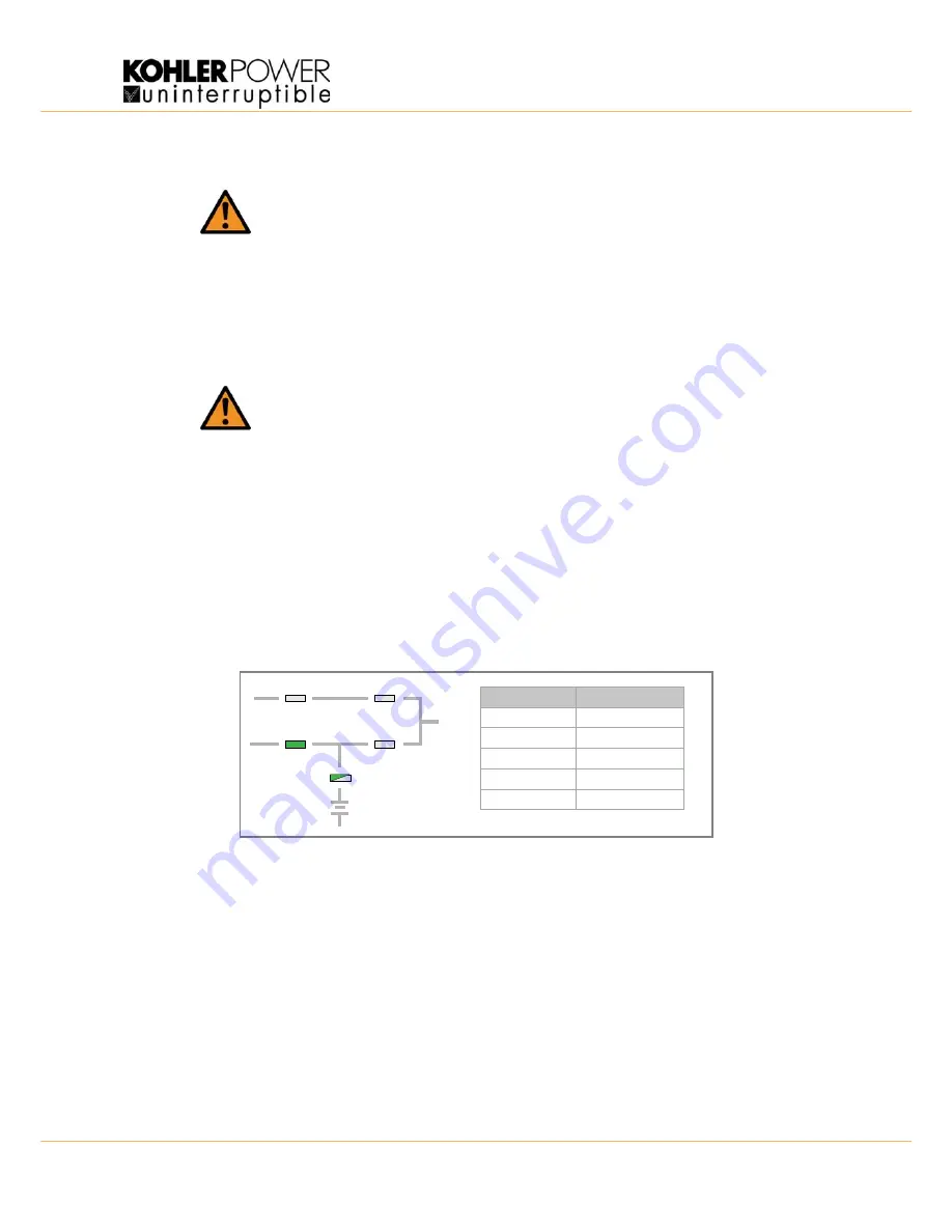
LED
Colour
LINE 1
Green
LINE 2
Off
BY PASS
Off
INVERTER
Off
BATTERY
Green Flashing
LINE 1
LINE 2
BY PASS
INVERTER
BATTERY
LOAD
Summary of Contents for PW 9000DPA
Page 1: ...User Manual Pioneering solutions for total power protection Kohler PW 9000DPA ...
Page 2: ......
Page 8: ...iv UPS306 01 00 PowerWAVE 9000 DPA User Manual Dated 01 06 2010 ...
Page 10: ...1 Safety 1 2 UPS306 01 00 PowerWAVE 9000 DPA User Manual Dated 01 06 2010 ...
Page 18: ...2 Description 2 8 UPS306 01 00 PowerWAVE 9000 DPA User Manual Dated 01 06 2010 ...
Page 76: ...7 Options 7 6 UPS306 01 00 PowerWAVE 9000 DPA User Manual Dated 01 06 2010 ...
Page 85: ...UPS306 01 00 PowerWAVE 9000 DPA User Manual Dated 01 06 2010 8 9 8 Specifications ...
Page 86: ...8 Specifications 8 10 UPS306 01 00 PowerWAVE 9000 DPA User Manual Dated 01 06 2010 ...


