


UPS306-01-00 PowerWAVE 9000 DPA User Manual Dated 01-06-2010
3-19
3: Installation
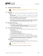
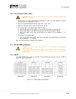
3.10 Connecting the batteries
3.10.1 Safety Notes
1.
For personal protection, ensure that the battery cables are connected under the following conditions:
a)
No mains voltage is present in the UPS.
b)
All the loads are disconnected.
c)
The UPS battery isolators are open and the external battery isolators are open in the external battery
cabinet (where used) – i.e. the terminals to which the battery cables are to be fitted are electrically
isolated.
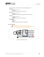
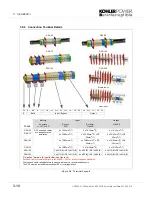
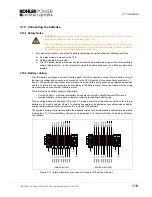
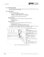
3.10.2 Battery cabling
The UPS battery comprises a number of battery blocks (30-50) connected in series to form a battery string of
the required voltage and capacity; and connected to the UPS module by three connections annotated ‘+’ ‘-’
and ‘N’. The plus and minus connections are taken from the battery string positive and negative extremities
and the ‘N’ terminal is connected to a point mid-way in the battery string (hence the reason why the string
must comprise an even number of battery blocks.
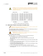
There are two basic battery supply configurations:
•
Common battery
– where several battery strings are connected in parallel to each UPS module.
•
Individual battery
– where each module is connected to individual battery string.
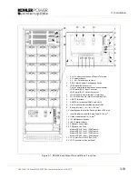
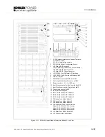
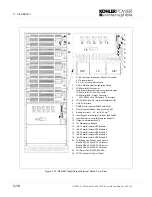
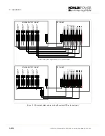
These configurations are depicted in Figure 3.13, which shows the alternative connections for internal
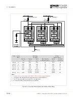
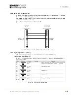
batteries in a 3-module cabinet. Figure 3.14 shows an example of the alternative connections when using an
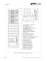
external battery cabinet (shown connected to a 5-module UPS cabinet).
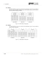
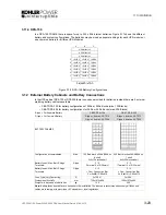
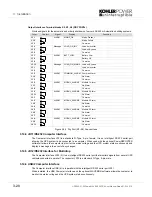
The available battery configurations within the standard internal and external battery cabinets are described
in paragraph 3.11
(Internal Battery Systems)
and paragraph 3.12
(External Battery Cabinets and Battery
Connections)
.
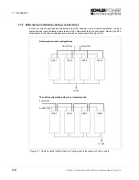
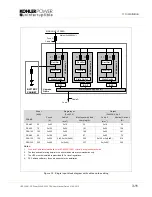
Figure 3.13 Internal battery connections (3-module UPS cabinet shown)
WARNING:
Opening or removing the UPS enclosure covers will create the risk of exposure to
dangerous voltages if power is connected to the UPS.
The final assembly and connection of the battery units must be carried out by (or under the
supervision of) the commissioning engineer. Do not attempt to complete the battery wiring or
close the battery isolators before system commissioning.
COMMON BATTERY
INDIVIDUAL BATTERIES
PE
1L1
2L1
UPS3 +
UPS2 +
UPS1 +
UPS3 N
UPS2 N
UPS1 N
UPS3
UP
S
2
UP
S
1
S
tr
ing 3 +
S
tr
ing 2 +
S
tr
ing 1 +
S
tr
ing 3 N
S
tr
ing 2 N
S
tr
ing 1 N
S
tr
ing 3
S
tr
ing 2
St
ri
n
g
1
PE
1L1
2L1
UPS3 +
UPS2 +
UPS1 +
UPS3 N
UPS2 N
UPS1 N
UPS3
UP
S
2
UP
S
1
S
tr
ing 3 +
S
tr
ing 2 +
S
tr
ing 1 +
S
tr
ing 3 N
S
tr
ing 2 N
S
tr
ing 1 N
S
tr
ing 3
S
tr
ing 2
St
ri
n
g
1
Summary of Contents for PW 9000DPA
Page 1: ...User Manual Pioneering solutions for total power protection Kohler PW 9000DPA ...
Page 2: ......
Page 8: ...iv UPS306 01 00 PowerWAVE 9000 DPA User Manual Dated 01 06 2010 ...
Page 10: ...1 Safety 1 2 UPS306 01 00 PowerWAVE 9000 DPA User Manual Dated 01 06 2010 ...
Page 18: ...2 Description 2 8 UPS306 01 00 PowerWAVE 9000 DPA User Manual Dated 01 06 2010 ...
Page 76: ...7 Options 7 6 UPS306 01 00 PowerWAVE 9000 DPA User Manual Dated 01 06 2010 ...
Page 85: ...UPS306 01 00 PowerWAVE 9000 DPA User Manual Dated 01 06 2010 8 9 8 Specifications ...
Page 86: ...8 Specifications 8 10 UPS306 01 00 PowerWAVE 9000 DPA User Manual Dated 01 06 2010 ...


