


UPS306-01-00 PowerWAVE 9000 DPA User Manual Dated 01-06-2010
4-3
4: Operation
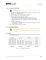
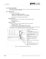
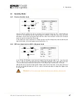
ON/OFF Start-up and shutdown buttons
The UPS may be switched ON or OFF by simultaneously pressing both
ON/OFF
keys on the control panel.
This is to prevent accidental UPS start-up or shutdown.
Note:
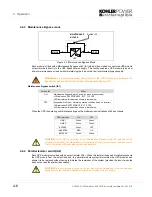
When the UPS is under normal operation, pressing the two
ON/OFF
simultaneously will immediately
shutdown the UPS. In a single module installation this will disconnect the UPS from the load. In a parallel
module system the UPS module will shutdown and the module will effectively be removed from the parallel
load bus; however, the load may or may-not transfer to the bypass supply in the remaining modules
depending on the available module redundancy. To shut down all the modules in a parallel system you must
press both
ON/OFF
buttons on every UPS cabinet!
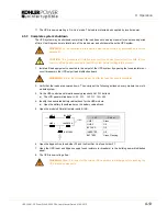
LOAD OFF in a PowerWAVE 9000 DPA Single module system
If, for security or emergency reasons, it is necessary to immediately disconnect the load from the UPS, press
the two red ON/OFF Buttons simultaneously. The simultaneous action of both buttons is necessary to avoid
any accidental manipulation.
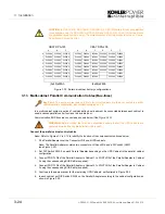
LOAD OFF in a PowerWAVE 9000 DPA Parallel module system
If, for security or emergency reasons, it is necessary to immediately disconnect the load from the UPS in a
multi-module system, the two ON/OFF buttons must be pressed simultaneously on one module and then
action repeated on all remaining modules sequentially.
4.3
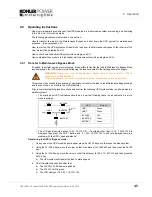
Description of the LCD
4.3.1 Status
screens
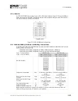
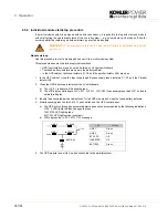
Note:
The ‘Unit’ number on the right hand side of the LCD indicates the cabinet number (in a multi-cabinet
system) together with the UPS module (slot) number within the cabinet. The maximum number of Module
units is 10 and the module slot number can vary from 1 to 5. The definition of a Module’s position is achieved
in the menu Service Set-Up.
For example:
Unit:05/3
indicates UPS module number 3 in system Cabinet number 5.
CAUTION: If the
ON/OFF
buttons are operated while the UPS is not in Maintenance Bypass it
will interrupt the load power supply.
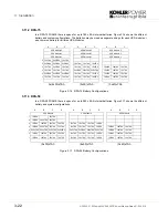
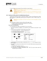
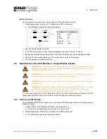
DESCRIPTION
LCD-DISPLAY
1.
Load is protected by UPS power Load is
supplied by inverter (Normal Operation).
LOAD
PROTECTED
Unit:01/1
2.
Load is not protected by UPS
Load is supplied by mains power (load on
bypass).
LOAD
NOT PROTECTED
Unit:01/1
3.
Load supply completely interrupted. UPS has
been switched off by “ON/OFF” buttons.
LOAD OFF
SUPPLY FAILURE
Unit:01/1
4.
UPS/module is not supplying load. The output
switch is open
LOAD DISCONNECTEDPARALLEL
SWITCH OPEN
Unit:01/1
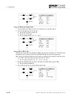
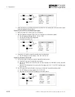
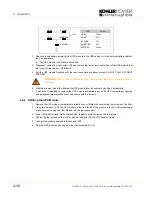
DESCRIPTION
LCD-DISPLAY
1.
Single Systems.
SYSTEM CONFIGURATION
SINGLE
Unit:01/1
2.
Parallel System eg. First Cabinet/Master
Modules no 2 in slot 2.
SYSTEM CONFIGURATION
PARALLEL
Unit:02/2
3.
Parallel System eg. Second Cabinet/Slave
Modules no 5 in slot 3.
LOAD OFF
SUPPLY FAILURE
Unit:05/3
4.
Parallel System eg. Second Cabinet/Slave
Modules no 6 in slot 2.
LOAD DISCONNECTEDPARALLEL
SWITCH OPEN
Unit:06/4
Summary of Contents for PW 9000DPA
Page 1: ...User Manual Pioneering solutions for total power protection Kohler PW 9000DPA ...
Page 2: ......
Page 8: ...iv UPS306 01 00 PowerWAVE 9000 DPA User Manual Dated 01 06 2010 ...
Page 10: ...1 Safety 1 2 UPS306 01 00 PowerWAVE 9000 DPA User Manual Dated 01 06 2010 ...
Page 18: ...2 Description 2 8 UPS306 01 00 PowerWAVE 9000 DPA User Manual Dated 01 06 2010 ...
Page 76: ...7 Options 7 6 UPS306 01 00 PowerWAVE 9000 DPA User Manual Dated 01 06 2010 ...
Page 85: ...UPS306 01 00 PowerWAVE 9000 DPA User Manual Dated 01 06 2010 8 9 8 Specifications ...
Page 86: ...8 Specifications 8 10 UPS306 01 00 PowerWAVE 9000 DPA User Manual Dated 01 06 2010 ...


