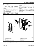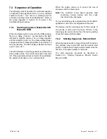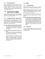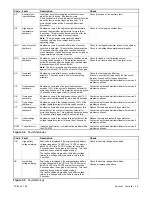
TP-6255 7/06
38
Section 5 Cooling System
5.9 Siphon Break
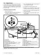
A siphon break prevents seawater entry into the engine
when the engine exhaust manifold outlet is less than
23 cm (9 in.) above the waterline of a fully-loaded,
shut-down craft. Use the following procedure to inspect
the siphon break.
Siphon Break Inspection Procedure:
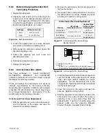
1. Stop the generator set.
2. Remove the retaining cap and lift out the reed valve
assembly for inspection. See Figure 5-9.
3. Use a light detergent to clean the reed valve to
remove residue and oxidation.
4. Check that the reed valve opening is clear.
5. Replace the siphon break if it is cracked or if the
reed valve material has hardened or deteriorated.
6. Install the reed valve into the mounting base with
the valve downward.
7. Install the retaining cap and finger-tighten only. Do
not overtighten.
Waterline
1
2
3
7
8
9
17
10
11
12
13
14
15
16
20
18
6
5
4
TP-5586-3
19
1. Mounting base
2. Retaining cap
3. Reed valve assembly
4. Silencer vertical lift 1.2 m (4 ft.) max.
5. Exhaust mixer elbow distance above waterline; if less than
23 cm (9 in.), siphon break is required
6. Siphon break distance above waterline 30.5 cm (1 ft.) min.
7. Siphon break
8. Exhaust mixer elbow
9. Heat exchanger (locations vary by model)
10. Seawater strainer
11. Seacock
12. Intake strainer
13. Engine-driven seawater pump
14. Exhaust hose pitch 1.3 cm per 30.5 cm (0.5 in./ft.) min.
15. Water lock (optional)
16. Silencer distance from exhaust mixer elbow 3 m (10 ft.) max.
17. Silencer (customer-supplied)
18. Exhaust hose pitch 1.3 cm per 30.5 cm (0.5 in./ft.) min.
19. Exhaust outlet distance above waterline 10 cm (4 in.) min.
20. Seawater outlet
NOTE: Consult the installation manual for complete explanation of dimensions and other installation considerations.
Figure 5-9
Siphon Break (Plastic “U” Type)
Summary of Contents for 6.5-27EFOZD
Page 1: ...Marine Generator Sets Models 8 32EOZD 6 5 27EFOZD TP 6255 7 06a Service ...
Page 12: ...TP 6255 7 06 12 Service Assistance Notes ...
Page 22: ...TP 6255 7 06 22 Section 1 Specifications Notes ...
Page 28: ...TP 6255 7 06 28 Section 3 Intake and Exhaust System Notes ...
Page 62: ...TP 6255 7 06 62 Section 7 Controller Notes ...
Page 78: ...TP 6255 7 06 78 Section 8 Component Testing and Adjustment Notes ...
Page 92: ...TP 6255 7 06 92 Section 10 Wiring Diagrams Notes ...
Page 100: ...TP 6255 7 06 100 ...
Page 101: ...TP 6255 7 06 101 ...
Page 102: ...TP 6255 7 06 102 ...
Page 103: ...TP 6255 7 06 103 ...

