TP-6255 7/06
32
Section 4 Fuel System
4.3 Fuel Pump
The fuel pump transfers fuel from a source to the
injection pump.
Fuel Pump Test Procedure:
1. Remove the two leads at the bottom of the fuel
pump. The pump terminals are labeled (--) and (+).
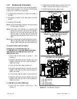
See Figure 4-5.
2. Connect the inlet side of the pump to a fuel source.
Disconnect the outlet hose from the fuel filter and
place the hose end in a container to catch the fuel.
3. Connect the positive (+) terminal of a 12-volt
battery to the positive terminal of the fuel pump.
Connect the negative terminal of the fuel pump to
the negative (--) terminal of the battery. You should
hear the pump operate and see fuel discharge from
the pump outlet. Replace the pump if it does not
operate.
4. Connect a pressure gauge to the outlet side of the
fuel pump. Repeat step 3
.
See Section 1 for the
specified fuel pump pressure ratings.
I-940
1
2
3
4
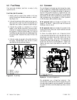
1. Fuel inlet
2. Negative (--) terminal
3. Positive (+) terminal
4. Fuel outlet
Figure 4-5
Fuel Pump
4.4 Governor
The centrifugal, mechanical governor keeps the engine
speed constant by automatically adjusting the amount
of fuel supplied to the engine according to changes in
the load. The governor requires no regular service. The
factory adjusts the governor during run-in, and further
adjustment should not be needed unless greatly varying
load conditions are encountered or if poor governor
control develops after extended usage.
60 Hz generator sets
are designed to operate in the
range of
57-63 Hz
(1800 rpm under full load and
1890 rpm under no load).
50 Hz generator sets
are designed to operate in the
range of 47-53 Hz (1500 rpm under full load and 1590
rpm under no load).
To check the engine speed, use a frequency meter
connected to the load leads or use a hand tachometer. If
adjustment is needed, loosen the locking nut on the
speed adjusting screw. Turn the screw clockwise to
increase the speed (and frequency). To decrease the
speed, turn the screw counterclockwise. Tighten the
locking nut when the correct setting is reached. See
Figure 4-6.
1
2
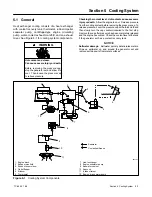
1. Speed adjusting screw
2. Locking nut
607146
Figure 4-6
Governor Adjustment
The generators use a 3-lead fuel solenoid.
This
solenoid has a white lead (P) which energizes the pull-in
coil only during cranking. During operation, the red lead
energizes the hold coil and the black lead is the common
ground.
Summary of Contents for 6.5-27EFOZD
Page 1: ...Marine Generator Sets Models 8 32EOZD 6 5 27EFOZD TP 6255 7 06a Service ...
Page 12: ...TP 6255 7 06 12 Service Assistance Notes ...
Page 22: ...TP 6255 7 06 22 Section 1 Specifications Notes ...
Page 28: ...TP 6255 7 06 28 Section 3 Intake and Exhaust System Notes ...
Page 62: ...TP 6255 7 06 62 Section 7 Controller Notes ...
Page 78: ...TP 6255 7 06 78 Section 8 Component Testing and Adjustment Notes ...
Page 92: ...TP 6255 7 06 92 Section 10 Wiring Diagrams Notes ...
Page 100: ...TP 6255 7 06 100 ...
Page 101: ...TP 6255 7 06 101 ...
Page 102: ...TP 6255 7 06 102 ...
Page 103: ...TP 6255 7 06 103 ...

