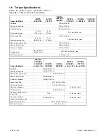


TP-6255 7/06
35
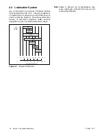
Section 5 Cooling System
5.5 Flush and Clean Cooling
System
For optimum protection, drain, flush, and refill the
cooling system at the interval listed in the service
schedule.
Pay special attention to the coolant level. When refilling
the cooling system, allow time for complete refill of the
engine water jacket.
Check the coolant level as
described in Section 5.4.
Flush and Clean Procedure:
1. Remove the water drain pipe plug located at the
heat exchanger and completely drain the system.
2. Remove the pressure cap to make draining easier.
3. Drain, clean, and flush the cooling system and the
coolant recovery tank with clean water.
4. Replace the water drain pipe plug.
5. Fill the cooling system with recommended coolant.
6. Replace the pressure cap.
5.6 Pressure Cap
Closed heat exchanger systems utilize a pressure cap
to raise the boiling point of the coolant, enabling proper
operating temperatures. If the cap leaks, replace it with
a cap of the same rating. See Section 1, Specifications.
The pressure cap typically has the pressure rating
stamped on the cap body.
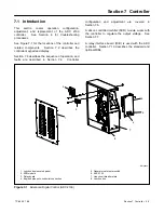
5.7 Impeller Inspection and
Replacement
The belt-driven seawater pump is located on the service
side of the generator set.
Check and change the
seawater pump impeller at the interval specified in the
service schedule. Follow the instructions included with
the impeller kit. If the instructions are not included with
the kit, use the following procedure.
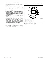
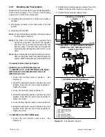
Impeller Inspection and Replacement Procedure:
1. Close the seacock.
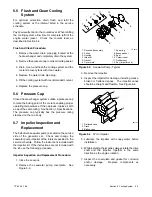
2. Remove the seawater pump coverplate.
See
Figure 5-3.
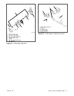
1
TP-5616
1. Drive shaft assembly
2. Pulley
3. Housing
4. Impeller
5. Gasket
6. Cover plate
7. Snap ring
8. Brass washer
9. Seal
10. Ceramic seat
11. Rubber seat
12. Key (impeller end)
2
3
4
5
6
9
10
12
8
7
11
Figure 5-3
Seawater Pump, Typical
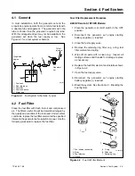
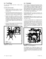
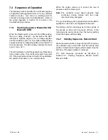
3. Remove the impeller.
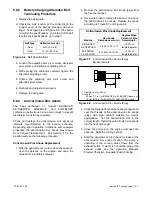
4. Inspect the impeller for damage, including cracks,
broken or flattened vanes.
The impeller vanes
should be straight and flexible. See Figure 5-4.
1
2
3
1. Flattened vane
2. Crack
3. Broken vane
607153
Figure 5-4
Worn Impeller
5. Lubricate the impeller with soapy water before
installation.
6. While installing the impeller, always rotate the drive
shaft and the impeller together in the same
direction as the engine rotation.
7. Inspect the coverplate and gasket for corrosion
and/or
damage.
Replace
components
as
necessary.
Summary of Contents for 6.5-27EFOZD
Page 1: ...Marine Generator Sets Models 8 32EOZD 6 5 27EFOZD TP 6255 7 06a Service ...
Page 12: ...TP 6255 7 06 12 Service Assistance Notes ...
Page 22: ...TP 6255 7 06 22 Section 1 Specifications Notes ...
Page 28: ...TP 6255 7 06 28 Section 3 Intake and Exhaust System Notes ...
Page 62: ...TP 6255 7 06 62 Section 7 Controller Notes ...
Page 78: ...TP 6255 7 06 78 Section 8 Component Testing and Adjustment Notes ...
Page 92: ...TP 6255 7 06 92 Section 10 Wiring Diagrams Notes ...
Page 100: ...TP 6255 7 06 100 ...
Page 101: ...TP 6255 7 06 101 ...
Page 102: ...TP 6255 7 06 102 ...
Page 103: ...TP 6255 7 06 103 ...