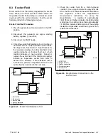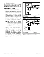
TP-6255 7/06
51
Section 7 Controller
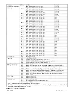
Parameter
Setting
Definition
Connect
Unit’s system voltage and
f
[
Single phase, 2 Wire, 60 Hz, 100 VAC
1Ph, 2W
y
g
frequency
[
Uu00
Single phase, 3 Wire, 60 Hz, 100 VAC
1Ph, 3W
Uu00
Single phase, 2 Wire, 60 Hz, 120 VAC
1Ph, 2W
Single phase, 3 Wire, 60 Hz, 120 VAC
1Ph, 3W
Uu01
Single phase, 3 Wire, 60 Hz, 120/240 VAC
1Ph, 3W
Uu01
Single phase, 3 Wire, 60 Hz, 120/240 VAC
Dogleg
Uu02
Single phase, 2 Wire, 50 Hz, 230 VAC
1Ph, 2W
Uu03
Three phase, 4 Wire, 50 Hz, 230/400 VAC
Wye
Uu04
Three phase, 4 Wire, 60 Hz, 277/480 VAC
Wye
Single phase, 2 Wire, 50 Hz, 100 VAC
1Ph, 2W
Uu05
Single phase, 3 Wire, 50 Hz, 100 VAC
1Ph, 3W
Uu05
Single phase, 2 Wire, 50 Hz, 110 VAC
1Ph, 2W
Single phase, 3 Wire, 50 Hz, 110 VAC
1Ph, 3W
Uu06
Single phase, 3 Wire, 50 Hz, 115/230 VAC
1Ph, 3W
Uu07
Single phase, 3 Wire, 50 Hz, 110/220 VAC
1Ph, 3W
Uu07
Single phase, 3 Wire, 50 Hz, 110/220 VAC
Dogleg
Uu08
Single phase, 3 Wire, 60 Hz, 100/200 VAC
1Ph, 3W
Uu09
Single phase, 3 Wire, 50 Hz, 100/200 VAC
1Ph, 3W
Uu10
Three phase, 4 Wire, 60 Hz, 120/240 VAC
Delta
Uu10
Three phase, 4 Wire, 60 Hz, 139/240 VAC
Wye
Uu11
Three phase, 4 Wire, 60 Hz, 120/208 VAC
Wye
Uu12
Single phase, 2 Wire, 50 Hz, 220 VAC
1Ph, 2W
Uu13
Single phase, 2 Wire, 50 Hz, 240 VAC
1Ph, 2W
Uu14
Three phase, 4 Wire, 50 Hz, 115/230 VAC
Delta
Uu15
Three phase, 4 Wire, 50 Hz, 110/220 VAC
Delta
Uu16
Three phase, 4 Wire, 60 Hz, 127/220 VAC
Wye
Uu17
Three phase, 4 Wire, 50 Hz, 110/190 VAC
Wye
Uu18
Three phase, 4 Wire, 50 Hz, 120/208 VAC
Wye
Uu19
Three phase, 4 Wire, 60 Hz, 220/380 VAC
Wye
Uu20
Three phase, 4 Wire, 60 Hz, 240/416 VAC
Wye
Uu20
Three phase, 4 Wire, 60 Hz, 230/400 VAC
Wye
Uu21
Three phase, 4 Wire, 50 Hz, 220/380 VAC
Wye
Uu22
Three phase, 4 Wire, 50 Hz, 240/416 VAC
Wye
Unit configuration
Uc00
Marine generator set
Engine type
Ec01
8--9EOZD/6.5--7EFOZD
g
yp
Ec02
10--20EOZD/9--17.5EFOZD and 24EOZD/20EFOZD
Ec07
28--32EOZD/23--27EFOZD (Units without the preheater option)
Ec09
23EOZD/20EFOZD (Units with the preheater option)
Engine data input types
(N
ti
i k
)
Ed00
All digital inputs
g
p
yp
(No magnetic pick-up)
Ed01
Digital:
Low coolant level and low oil pressure.
Analog:
Low coolant temperature
Ed02
Digital:
Low coolant level and low coolant temperature.
Analog:
Low oil pressure
Ed03 *
Digital:
Low coolant level.
Analog:
Low coolant temperature and low oil pressure
Ed08
Digital:
Low coolant temperature and low oil pressure.
Analog:
Low coolant level
Ed09
Digital:
Low oil pressure.
Analog:
Low coolant level and low coolant temperature
Ed10
Digital:
Low coolant temperature.
Analog:
Low coolant level and low oil pressure
Ed11
All analog inputs
Battery Voltage
Bt12
Battery voltage 12 VDC
y
g
Bt24
Battery voltage 24 VDC
Communications
Cn00
No CAN communications
Cn01
SAE J1939 (Used for ADC remote digital gauge)
Cn02
Future CANbus
* Factory default setting for 8--32EOZD and 6.5--27EFOZD marine models.
[
Check the generator set spec sheet for voltage configurations applicable to each model. Use voltage/frequency parameters Uu07--Uu22 only
with ADC application program version 1.20 or higher.
Figure 7-6
Controller Parameters
Summary of Contents for 6.5-27EFOZD
Page 1: ...Marine Generator Sets Models 8 32EOZD 6 5 27EFOZD TP 6255 7 06a Service ...
Page 12: ...TP 6255 7 06 12 Service Assistance Notes ...
Page 22: ...TP 6255 7 06 22 Section 1 Specifications Notes ...
Page 28: ...TP 6255 7 06 28 Section 3 Intake and Exhaust System Notes ...
Page 62: ...TP 6255 7 06 62 Section 7 Controller Notes ...
Page 78: ...TP 6255 7 06 78 Section 8 Component Testing and Adjustment Notes ...
Page 92: ...TP 6255 7 06 92 Section 10 Wiring Diagrams Notes ...
Page 100: ...TP 6255 7 06 100 ...
Page 101: ...TP 6255 7 06 101 ...
Page 102: ...TP 6255 7 06 102 ...
Page 103: ...TP 6255 7 06 103 ...

