4-10
INSTALLATION
ADJUSTMENT OF TD STROKE
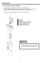
The stroke can be adjusted from 120mm at the minimum to the 200mm at the maximum by
changing the position of the Limit switches.
Turn off the power for the motor before adjusting the Limit
switches.
•
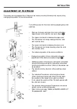
Remove 4 screws and open the cover so that the
Upper/Lower Limit switches are seen. (figure 1 )
•
The Upper Limit switch indicates the upper end.
•
The Transducer unit stops raising when the Joint
arm reaches here.
•
The Lower Limit switch indicates the lower end.
•
The Transducer unit stops lowering when the Joint
arm reaches here.
•
The initial set position of the stroke is 200mm.
•
Change the position of the Limit switch when the
adjustment of the stroke is required. (figure 2 )
•
Shift the position of the Upper Limit switch to the third
hole from the top and Lower Limit switch to the third
hole from the bottom so that 120mm of the stroke can
be provided.
•
Pay attention to the direction of the switches when
shifted.
•
The retracted Transducer unit should be at least
15mm above the lowest part of the TD tank when
the position of the Upper Limit switch is shifted.
•
If not, adjust the position of the TD shaft upward with
the Joint arm loosen.
•
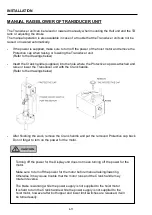
The position of the retracted Transducer unit and its
stroke can be confirmed manually.
•
Refer to the next page
“MANUAL RAISE/LOWER OF
TRANSDUCER UNIT
.”
Summary of Contents for ESR-145
Page 1: ......
Page 2: ......
Page 3: ......
Page 4: ......
Page 6: ... This page intentionally left blank ...
Page 14: ...8 This page intentionally left blank ...
Page 59: ... This page intentionally left blank ...
Page 62: ...4 3 INSTALLATION DIMENSIONS HULL UNIT DISPLAY UNIT Unit mm inch ...
Page 75: ... This page intentionally left blank ...
Page 85: ......
Page 86: ......


