4-1
Chapter 4
INSTALLATION
This chapter explains the installation for Display unit and Hull unit.
INSTALLATION POSITION
…………………………...……………….
4 - 2
DIMENSIONS
………………………………………………………..………
4 - 3
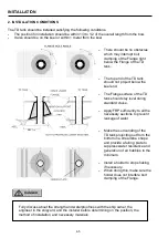
TD TANK INSTALLATION
…………………………...…………….….. 4 - 4
1. Maintenance
Space……………………………………………..
4 - 4
2. Installation
Conditions…………………………………..…..….
4 - 5
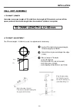
HULL UNIT ASSEMBLY
…………………………...………………….. 4 - 6
1. TD shaft
Length……….………………………….…………....
4 - 6
2. TD shaft
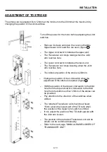
Adjustment………………………………….…..…....
4 - 6
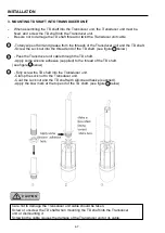
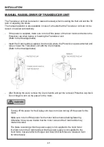
3. Mounting TD shaft into Transducer unit
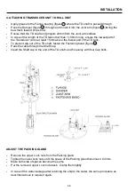
4. Attaching Transducer unit to Hull unit
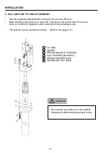
5. Hull unit and TD tank
Attachment……………………..……..
4 - 9
Summary of Contents for ESR-145
Page 1: ......
Page 2: ......
Page 3: ......
Page 4: ......
Page 6: ... This page intentionally left blank ...
Page 14: ...8 This page intentionally left blank ...
Page 59: ... This page intentionally left blank ...
Page 62: ...4 3 INSTALLATION DIMENSIONS HULL UNIT DISPLAY UNIT Unit mm inch ...
Page 75: ... This page intentionally left blank ...
Page 85: ......
Page 86: ......

