4-8
INSTALLATION
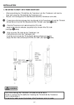
4. ATTACHING TRANSDUCER UNIT TO HULL UNIT
•
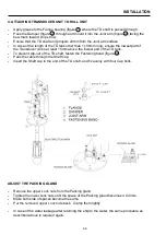
Apply grease to the Flange bearing (figure 1 ) where the TD shaft is passed through.
•
Pass the Damper (figure 2 ) through and mount it into the Joint arm (figure 3 ) facing the
bow mark toward
ship’s bow.
•
Ensure that the TD shaft end projects 20mm from the Joint arm surface.
•
In case of the length of the TD tank other than 1,180mm long, ensure the lowest part of
the Transducer unit is at least 15mm above the lowest part of the TD tank.
•
To prevent slip-out of the TD shaft, fasten the Fastening band (figure 4 ).
•
Pass the cable through the Shaft cap.
•
Insert the Shaft cap in the end of the TD shaft, and fix evenly with four Cap bolts.
ADJUST THE PACKING GLAND
•
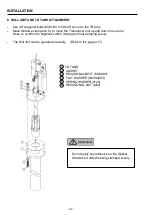
Remove the upper Lock nuts from the Packing gland.
•
Tighten the lower Lock nuts until the space of the Packing gland becomes 4 to 5mm.
•
Make both side of spaces become the same.
•
Put the removed upper Lock nuts back. Clamp them tightly.
•
In case of the water leakage after returning the ship to the water, the same procedure as
described above is required again.
Summary of Contents for ESR-145
Page 1: ......
Page 2: ......
Page 3: ......
Page 4: ......
Page 6: ... This page intentionally left blank ...
Page 14: ...8 This page intentionally left blank ...
Page 59: ... This page intentionally left blank ...
Page 62: ...4 3 INSTALLATION DIMENSIONS HULL UNIT DISPLAY UNIT Unit mm inch ...
Page 75: ... This page intentionally left blank ...
Page 85: ......
Page 86: ......


