Chapter 1 Installation
CVS-705D/707D
1-12
0092607052-03
1.5.2 Flush-mount installation
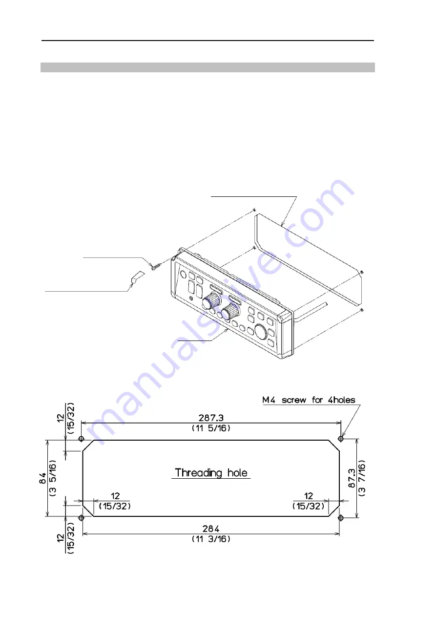
(1) Make a square hole at the location to be installed (See Fig.1.14)
(2) Remove 4 plastic corner guard caps of the Operation unit (These can be easily pulled out
upwards).
(3) Confirm that the Operation unit matches the square hole. If not matches, correct the
square hole.
(4) Put the Operation unit and connected cable in the square hole, and set it to the position in
which the Operation unit becomes parallel to the install panel. (Fig.1-13)
(5) Install the Operation unit in the installing location (square hole) and fix it with 4 tapping
screws (4mm) (M4 or pan-head). (Prepare 4 mm screws suitable for thickness of
installing location.)
(6) Install the corner guard caps removed in step (2).
Fig. 1.13 Flush-mount installation of Operation unit
Fig. 1.14 Hole for flush-mount installation of Operation unit
Attention: Thickness of panel: 10mm (max)
M4 Screw (4pcs)
Corner guard cap (4pcs)
Operation unit
Unit: mm (inch)
Summary of Contents for CVS-705D
Page 1: ......
Page 2: ......
Page 15: ...CVS 705D 707D Dimensions 0092607052 03 xiii Dimensions Display unit of CVS 705D Unit mm inch ...
Page 16: ...Dimensions CVS 705D 707D xiv 0092607052 03 Processor unit of CVS 707D Unit mm inch ...
Page 17: ...CVS 705D 707D Dimensions 0092607052 03 xv 17 inch LCD Monitor of CVS 707D Unit mm inch ...
Page 18: ...Dimensions CVS 705D 707D xvi 0092607052 03 Operation unit of CVS 705D 707D Unit mm inch ...
Page 20: ...Specifications CVS 705D 707D xviii 0092607052 03 This page intentionally left blank ...
Page 66: ...Chapter 2 Adjustment CVS 705D 707D 2 8 0092607052 03 This page intentionally left blank ...
Page 73: ......
Page 74: ......


