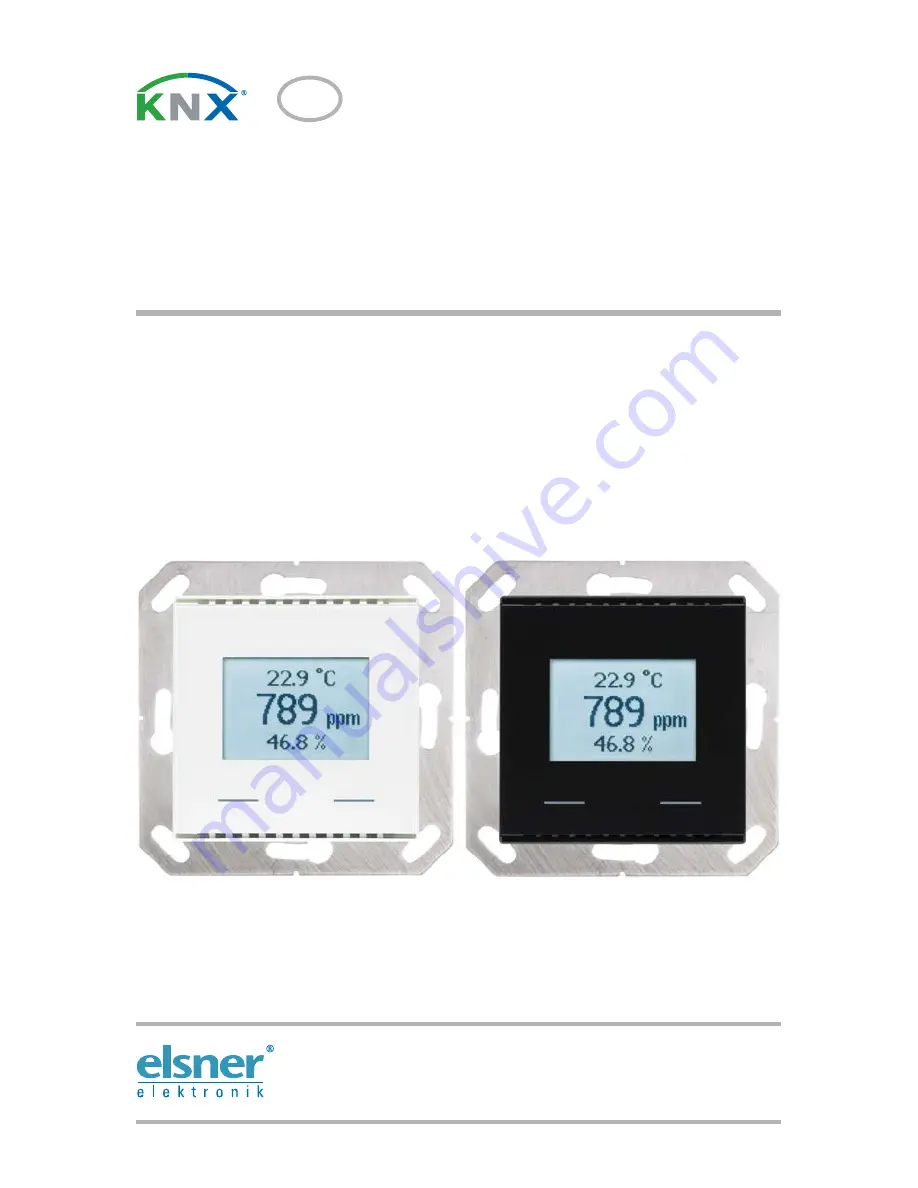
KNX AQS/TH-UP Touch
Combined indoor sensor
Item numbers 70619 (black), 70620 (pure white)
EN
Installation and Ad justment
Page 1: ...KNX AQS TH UP Touch Combined indoor sensor Item numbers 70619 black 70620 pure white EN Installation and Adjustment ...
Page 2: ......
Page 3: ...l 12 4 1 List of all communications objects 12 5 Parameter setting 23 5 1 Behaviour on power failure restoration of power 23 5 2 General settings 23 5 3 Temperature value 23 5 4 Temperature threshold values 24 5 4 1 Threshold value 1 2 3 24 5 4 1 1 Threshold value 24 5 4 1 2 Switching output 25 5 4 1 3 Block 26 5 5 Temperature PI control 26 5 5 0 1 General control 26 5 5 1 General set point values...
Page 4: ...d 45 5 12 CO2 parameter settings 45 5 13 CO2 threshold values 46 5 13 1 Threshold value 1 2 3 4 46 5 13 1 1 Threshold value 46 5 13 1 2 Switching output 47 5 13 1 3 Block 48 5 14 CO2 PI control 49 5 14 0 1 General control 49 5 14 0 2 Controller setpoint 49 5 14 0 3 Ventilation control 50 5 15 Variable comparator 51 5 15 1 Control variable comparator 1 2 51 5 16 Logic 52 5 16 0 1 AND logic 52 5 16 ...
Page 5: ...leshooting of the device must only be carried out by a competent electrician Safety advice Safety advice for working on electrical connections components etc DANGER indicates an immediately hazardous situation which will lead to death or severe injuries if it is not avoided WARNING indicates a potentially hazardous situation which may lead to death or severe injuries if it is not avoided CAUTION i...
Page 6: ... is completed with a frame of the switching series installed in the building and thus merges with the interior Functions Measurement of CO2 concentration of the air of temperature and air humidity absolute and relative calculation of the dew point Mixed values from own measured values and external values proportions can be set in percentage Display 1 3 rows own values or values received from the b...
Page 7: ...ounting In wall wall mounting in socket Ø 60 mm 42 mm deep resp cavity wall socket for hole Ø 68 mm Protection category IP 20 Dimensions Housing approx 55 x 55 W x H mm mounting depth approx 8 mm base plate approx 71 x 71 W x H mm Total weight approx 55 g Ambient temperature Operation 0 50 C storage 10 60 C Ambient air humidity max 95 RH avoid bedewing Operating voltage KNX bus voltage Bus current...
Page 8: ...only be performed by an electrician CAUTION Live voltage There are unprotected live components inside the device National legal regulations are to be followed Ensure that all lines to be assembled are free of voltage and take precautions against accidental switching on Do not use the device if it is damaged Take the device or system out of service and secure it against unintentional use if it can ...
Page 9: ...tallation location please ensure that the measurement results are affected as little as possible by external influences Possible sources of interference include Direct sunlight Drafts from windows and doors Draft from ducts which lead from other rooms or from the outside to the junction box in which the sensor is mounted Warming or cooling of the building structure on which the sensor is mounted e...
Page 10: ...ing with the notches on to the metal frame so that device and frame are fixed 2 5 Notes on mounting and commissioning Never expose the device to water e g rain or dust This can damage the electronics You must not exceed a relative humidity of 95 Avoid condensation After the bus voltage has been applied the device will enter an initialisation phase lasting a few seconds During this phase no informa...
Page 11: ... setting selected the mode display will only display show the current target value or the base target value setting with scale display The manually adjustable range can be set in the ETS The following display options are available Fig 3 Mode display with current target value and or base target value Fig 4 Mode display with scale display for adjusting the base target value The control position in t...
Page 12: ...uppressed for Priority 1 operating modes The individual operating modes can also be locked for manual selection in the ETS Comfort mode Comfort present target temperature will be used Standby mode Standby absent during day target temperature will be used Eco mode Night target temperature will be used Building protection mode Building protection target temperature will be used The symbol will blink...
Page 13: ...n Ambient temperature in the current mode is increased The sep size is defined in the ETS 0 1 C to 5 C Change mode press left or right button longer than 2 secs Changes between the operating modes Comfort Standby Eco and Building Protection if deblocked in the ETS Extend Comfort mode in Eco mode press both buttons at the same time longer than 2 secs Switches from Eco to Comfort mode again for a ce...
Page 14: ...alfunction Output R CT 1 1 DPT_Switch 1 Bit 3 Outside temperature reading Input WC 9 1 DPT_Value_Temp 2 Bytes 4 Inside temperature reading Output R CT 9 1 DPT_Value_Temp 2 Bytes 5 Overall temperature reading Output R CT 9 1 DPT_Value_Temp 2 Bytes 6 Min max temperature value request Input WC 1 17 DPT_Trigger 1 Bit 7 Minimum temperature reading Output R CT 9 1 DPT_Value_Temp 2 Bytes 8 Maximum temper...
Page 15: ... Bit 22 Temp threshold value 3 Absolute value Input Output RWC T 9 1 DPT_Value_Temp 2 Bytes 23 Temp threshold value 3 1 0 Input WC 1 2 DPT_Bool 1 Bit 24 Temp threshold value 3 Switching delay from 0 to 1 Input WC 9 010 DPT_Value_Time 2 Bytes 25 Temp threshold value 3 Switching delay from 1 to 0 Input WC 9 010 DPT_Value_Time 2 Bytes 26 Temp threshold value 3 Switching output Output R CT 1 1 DPT_Swi...
Page 16: ... 2 Bytes 45 TR_1_ Target value Eco heating 1 0 Input WC 1 1 DPT_Switch 1 Bit 46 TR_1_ Target value Eco cooling Input Output RWC T 9 1 DPT_Value_Temp 2 Bytes 47 TR_1_ Target value Eco cooling 1 0 Input WC 1 1 DPT_Switch 1 Bit 48 TR_1_ Control variable heating stage 1 Output R CT 5 1 DPT_Scaling 1 Byte 49 TR_1_ Control variable heating stage 2 Output R CT 5 1 DPT_Scaling 1 Byte 50 TR_1_ Control vari...
Page 17: ...1 Switch ing delay from 0 to 1 Input WC 9 010 DPT_Value_Time 2 Bytes 69 Humidity threshold value 1 Switch ing delay from 1 to 0 Input WC 9 010 DPT_Value_Time 2 Bytes 70 Humidity threshold value 1 Switch ing output Output R CT 1 1 DPT_Switch 1 Bit 71 Humidity threshold value 1 Switch ing output block Input WC 1 2 DPT_Bool 1 Bit 72 Humidity threshold value 2 Abso lute value Input Output RWC T 9 7 DP...
Page 18: ...mperature Output R CT 9 1 DPT_Value_Temp 2 Bytes 88 Coolant temp Threshold value Output R CT 9 1 DPT_Value_Temp 2 Bytes 89 Coolant temp Actual value Input WC 9 1 DPT_Value_Temp 2 Bytes 90 Coolant temp Offset change 1 0 Input WC 1 2 DPT_Bool 1 Bit 91 Coolant temp Switching delay from 0 to 1 Input WC 9 010 DPT_Value_Time 2 Bytes 92 Coolant temp Switching delay from 1 to 0 Input WC 9 010 DPT_Value_Ti...
Page 19: ...DPT_Switch 1 Bit 109 CO2 threshold value 1 Switching output block Input WC 1 2 DPT_Bool 1 Bit 110 CO2 threshold value 2 Absolute value Input Output RWC T 9 8 DPT_Value_AirQua lity 2 Bytes 111 CO2 threshold value 2 1 0 Input WC 1 2 DPT_Bool 1 Bit 112 CO2 threshold value 2 Switching delay from 0 to 1 Input WC 9 010 DPT_Value_Time 2 Bytes 113 CO2 threshold value 2 Switching delay from 1 to 0 Input WC...
Page 20: ... 1 Bit 129 CO2 controller Target value Input Output RWC T 9 8 DPT_Value_AirQua lity 2 Bytes 130 CO2 controller Target value 1 0 Input WC 1 2 DPT_Bool 1 Bit 131 CO2 controller Control variable ventilation stage 1 Output R CT 5 1 DPT_Scaling 1 Byte 132 CO2 controller Control variable ventilation stage 2 Output R CT 5 1 DPT_Scaling 1 Byte 133 CO2 controller Ventilation 1 status 1 ON 0 OFF Output R CT...
Page 21: ...ol 1 Bit 149 AND logic 1 1 bit switching output Output R CT 1 1 DPT_Switch 1 Bit 150 AND logic 1 8 bit output A Output R CT 5 5 xxx 1 Byte 151 AND logic 1 8 bit output B Output R CT 5 5 xxx 1 Byte 152 AND logic 1 Block Input WC 1 2 DPT_Bool 1 Bit 153 AND logic 2 1 bit switching output Output R CT 1 1 DPT_Switch 1 Bit 154 AND logic 2 8 bit output A Output R CT 5 5 xxx 1 Byte 155 AND logic 2 8 bit o...
Page 22: ...output B Output R CT 5 5 xxx 1 Byte 188 OR logic 2 Block Input WC 1 2 DPT_Bool 1 Bit 189 OR logic 3 1 bit switching output Output R CT 1 1 DPT_Switch 1 Bit 190 OR logic 3 8 bit output A Output R CT 5 5 xxx 1 Byte 191 OR logic 3 8 bit output B Output R CT 5 5 xxx 1 Byte 192 OR logic 3 Block Input WC 1 2 DPT_Bool 1 Bit 193 OR logic 4 1 bit switching output Output R CT 1 1 DPT_Switch 1 Bit 194 OR log...
Page 23: ...2 DPT_Bool 1 Bit 214 Logic input 15 Input WC 1 2 DPT_Bool 1 Bit 215 Logic input 16 Input WC 1 2 DPT_Bool 1 Bit 220 Display contrast 1 higher 0 lower Input WC 1 1 DPT_Switch 1 Bit 230 Date for display Input WCT 11 1 DPT_Date 3 Bytes 231 Time for display Input WCT 10 1 DPT_TimeOfDay 3 Bytes 232 8 bit object 1 for display Input WC 5 5 xxx 1 Byte 233 8 bit object 2 for display Input WC 5 5 xxx 1 Byte ...
Page 24: ...es 246 Pushbutton 1 Scenario Output R CT 5 5 xxx 1 Byte 247 Pushbutton 2 long term Output R CT 1 8 DPT_UpDown 1 Bit 248 Pushbutton 2 short term Output R CT 1 10 DPT_Start 1 Bit 249 Pushbutton 2 switching Input Output R CT 1 1 DPT_Switch 1 Bit 250 Pushbutton 2 Relative dimming Input Output RWC T 3 7 DPT_Control_Dim ming 4 Bit 251 Pushbutton 2 encoder 8 bit Output R CT 5 5 xxx 1 Byte 252 Pushbutton ...
Page 25: ...be sent 5 3 Temperature value Use Offsets to adjust the readings to be sent The unit can calculate a mixed value from its own reading and an external value Set the mixed value calculation if desired If an external value is used all of the following settings are referred to the total value Send delay after power up and programming for Measured values 5 s 2 h Threshold values and switching outputs 5...
Page 26: ...setting via objects is ignored Set the threshold value directly in the application program using parameters or define them via the bus using a communication object Threshold value setting via parameter Set the threshold values and hysteresis directly Threshold value setting via a communication object Define how the threshold value is to be received from the bus Basically a new value can be receive...
Page 27: ...r power supply restoration and programming Start threshold value in 0 1 C valid until first communication 300 800 200 Object value limit min in 0 1 C 300 800 Object value limit max in 0 1 C 300 800 Type of threshold value change Absolute value Increase decrease Increment upon increase decrease change 0 1 C 5 C 1 C Hysteresis in of the threshold value 0 50 20 When the following conditions apply the...
Page 28: ...start up as the factory settings are always used until the 1st communication setting via objects is ignored Use switching output block No Yes Analysis of the blocking object At value 1 block At value 0 release At value 0 block At value 1 release Blocking object value before 1st communication 0 1 Behaviour of the switching output On block Do not send message send 0 send 1 On release with 2 seconds ...
Page 29: ...AC mode Prio 1 for central switching with higher priority The objects are coded as follows 0 Auto 1 Comfort 2 Standby 3 Eco 4 Building Protection Alternatively you can use three objects with one object switching between eco and standby mode and the two others activating comfort mode and frost heat protection mode respectively The comfort object blocks the eco standby object and the frost heat prot...
Page 30: ...elect the setting separately with switching object Systems used for cooling in the summer and for heating in the winter can thus be switched from one to the other If you are using the basic value only the deviation from the comfort set point value is listed for the other modes e g 2 C less for standby mode Send control variable on change on change and periodically from change in absolute 1 10 2 Cy...
Page 31: ...s well as a temperature range in which the nominal value may be modified If set point values are entered separately If the comfort setpoint value is used as a basis If the comfort setpoint value is used as a basis the reduction increment of the value is set Grading for set point changes in 0 1 C 1 50 10 Saving set point value s not after voltage recovery after voltage recovery and programming Comf...
Page 32: ...y used for night mode If setpoint values are entered separately A starting setpoint value is defined as well as a temperature range in which the setpoint value may be changed Dead zone between heating and cooling in 0 1 C only if both heating AND cooling are used 1 100 50 Starting heating setpoint in 0 1 C valid until 1st communication 300 800 180 Starting heating setpoint in 0 1 C valid until 1st...
Page 33: ... control variable for heating and cooling If the 2nd level has a common control variable you also determine the control mode of the 2nd level here When using the control variable for a 4 6 way valve the following applies 0 100 heating 66 100 control variable OFF 50 control variable 0 100 cooling 33 0 control variable Reduce heating setpoint in 0 1 C for heating 0 200 50 Increase cooling setpoint i...
Page 34: ...rom the set point value In case of a short reset time the control responds with a fast increase of the control variable In case of a long reset time the control responds somewhat less urgently and needs longer until the necessary control variable for the setpoint value deviation is reached You should set the time appropriate to the heating system at this point observe man ufacturer s instructions ...
Page 35: ...uent on off switching of temperatures in the threshold range If separate control variables are used select whether the control variable of the 2nd level is a 1 bit object on off or an 8 bit object on with percentage off Control type PI control Setting of the controller by Controller parameter specified applications Application Warm water heating Floor heating Convection unit Electric heating Maxim...
Page 36: ...om the setpoint value which reaches maximum variable value i e the point at which maximum cooling power is activated The reset time shows how quickly the controller responds to deviations from the set point value In case of a short reset time the control responds with a fast increase of the control variable In case of a long reset time the control responds somewhat less urgently and needs longer u...
Page 37: ...ent on off switching of temperatures in the threshold range If separate control variables are used select whether the control variable of the 2nd level is a 1 bit object on off or an 8 bit object on with percentage off When blocked the control variable shall not be sent send a specific value Value in if a value is sent 0 100 Control type PI control Setting of the controller by Controller parameter...
Page 38: ...ing The minimum and maximum readings can be saved and sent to the bus Use the Reset humidity min max value object to reset the values to the current readings The values are not retained after a reset 5 7 Humidity threshold values Activate the required air humidity threshold values The menus for setting the thresh old values are displayed When blocked the control variable shall not be sent send a s...
Page 39: ...During initial commissioning a threshold value must be defined which will be valid until the first communication with a new threshold value For units which have already been taken into service the last communicated threshold value can be used Basically a humidity range is specified in which the threshold value can be changed object value limit A set threshold value will be retained until a new val...
Page 40: ...low 1 TV below 1 TV hyst above 0 TV below 0 TV hyst above 1 Delays can be set via objects in seconds No Yes Switching delay from 0 to 1 If delay can be set via objects valid until 1st communication None 1 s 2 s 5 s 10 s 2 h Switching delay from 1 to 0 If delay can be set via objects valid until 1st communication None 1 s 2 s 5 s 10 s 2 h Switching output sends on change on change to 1 on change to...
Page 41: ...itoring using an actuator with this setting Switching output sends on change Do not send message Send switching output status Switching output sends on change to 1 Do not send message if switching output 1 send 1 Switching output sends on change to 0 Do not send message if switching output 0 send 0 Switching output sends on change and periodically Send switching output status Switching output send...
Page 42: ...bus Basically a new value can be received or simply a command to increase or decrease A set setpoint value will be retained until a new value or a change is transferred The current value is saved so that it is retained in the event of a power supply failure and will be available once the power supply is restored Setpoint value setting using parameter Set the threshold values and hysteresis directl...
Page 43: ...ws how quickly the controller responds to deviations from the set point value In case of a short reset time the control responds with a fast increase of the control variable In case of a long reset time the control responds somewhat less urgently and needs longer until the necessary control variable for the setpoint value deviation is reached You should set the time appropriate for the humidificat...
Page 44: ...int temperature offset Set in which cases offset received via object is to be retained Please note that the set ting After power supply restoration and programming should not be used for the in itial start up as the factory settings are always used until the first communication set ting via objects is ignored During initial commissioning an offset must be defined which is valid until the first com...
Page 45: ...s of the threshold value in for setting in 0 50 20 Threshold value sends never periodically on change on change and periodically At and above change of if sent on change 0 1 C 0 2 C 0 5 C 1 0 C 2 0 C 5 0 C Send cycle if sent periodically 5 s 10 s 30 s 1 min 2 h When the following conditions apply the output is TV Threshold value TV above 1 TV hyst below 0 TV above 0 TV hyst below 1 TV below 1 TV h...
Page 46: ...0 send 1 On release with 2 seconds release delay Dependent on the Switching output sends setting Switching output sends on change Do not send message Send switching output status Switching output sends on change to 1 Do not send message if switching output 1 send 1 Switching output sends on change to 0 Do not send message if switching output 0 send 0 Switching output sends on change and periodical...
Page 47: ...f the sensor is faulty Use Offsets to adjust the readings to be sent The unit can calculate a mixed value from its own reading and an external value Set the mixed value calculation if desired If an external portion is used all of the following settings threshold values etc are related to the overall reading Use comfort field No Yes Sending pattern never periodically on change on change and periodi...
Page 48: ...d pro gramming should not be used for the initial start up as the factory settings are always used until the first communication setting via objects is ignored Set the threshold value directly in the application program using parameters or define them via the bus using a communication object Threshold value setting using parameters Set the threshold values and hysteresis directly Threshold value s...
Page 49: ...witching delay can be set using objects or directly as a parameter Threshold value setting using Parameter Communication objects The value communicated last shall be maintained never after power supply restoration after power supply restoration and programming Start threshold value in 0 1 C valid until first communication 0 5000 1200 Limitation of object value min in ppm 0 5000 Limitation of objec...
Page 50: ... block No Yes Analysis of the blocking object At value 1 block At value 0 release At value 0 block At value 1 release Blocking object value before first communi cation 0 1 Behaviour of the switching output On block Do not send message send 0 send 1 On release with 2 seconds release delay Dependent on the Switching output sends setting Switching output sends on change Do not send message Send switc...
Page 51: ...tus object shows the current status of the output variable 0 OFF 0 ON and can for example be used for visualisation Controller setpoint The setpoint values can be set directly in the application program using parameters or be defined via the bus using a communication object Use control Yes No Type of control One stage ventilation Two stage ventilation Behaviour of the blocking object with value 1 ...
Page 52: ...ure and will be available once the power supply is restored Ventilation control Depending on the control mode one and or two setting sections for the ventilation stages are displayed For two stage ventilation the setpoint value difference between the two stages must be defined i e the setpoint value which when exceeded triggers the switch to the 2nd level Specified setpoint using Parameter Communi...
Page 53: ...able follows the rule again 5 15 Variable comparator The two integrated control variable comparators can output maximum minimum and median values 5 15 1 Control variable comparator 1 2 Determine what the control variable comparator should output and activate the input objects to be used Send behaviour and blocks can also be set Maximum control variable is reached at setpoint value actual differenc...
Page 54: ...ch logic output may transmit one 1 bit or two 8 bit objects Determine what the out put should send if logic 1 and 0 Analysis of the blocking object at value 1 block at value 0 release at value 0 block at value 1 release Blocking object value before 1st communication 0 1 Behaviour of the switching output With blocking do not send message Send value Sent value in 0 100 Use logic inputs Yes No Object...
Page 55: ...e a 1 Bit object two 8 bit objects Output value if logic 1 1 0 Output value if logic 0 1 0 Object type Value 0 255 Percent 0 100 Angle 0 360 Scene call up 0 127 Output value object A if logic 1 0 255 100 360 127 1 Output value object B if logic 1 0 255 100 360 127 1 Output value object A if logic 0 0 255 100 360 127 0 Output value object B if logic 0 0 255 100 360 127 0 Send pattern on change of l...
Page 56: ...c input 6 inverted Logic input 7 Logic input 7 inverted Logic input 8 Logic input 8 inverted Logic input 9 Logic input 9 inverted Logic input 10 Logic input 10 inverted Logic input 11 Logic input 11 inverted Logic input 12 Logic input 12 inverted Logic input 13 Logic input 13 inverted Logic input 14 Logic input 14 inverted Logic input 15 Logic input 15 inverted Analysis of the blocking object At v...
Page 57: ...us heating 1 Temp control status heating 1 inverted Temp control status heating 2 Temp control status heating 2 inverted Temp control status cooling 1 Temp control status cooling 1 inverted Temp control status cooling 2 Temp control status cooling 2 inverted Switching output humidity 1 Switching output humidity 1 inverted Switching output humidity 2 Switching output humidity 2 inverted Humidity co...
Page 58: ...2 inverted AND logic output 3 AND logic output 3 inverted AND logic output 4 AND logic output 4 inverted 5 17 Display Adjust the display settings here Set contrast and number of lines as well as the type of temperature target value display Use display lighting No Yes Brightness in up to 1 Communication 0 255 100 Lighting always on only when operating Switch off delay after operation until 1st comm...
Page 59: ...ar chart with count Basic setpoint as bar chart with range Basic setpoint as bar chart with range and count Display duration in seconds for Temperature controller display 2 240 5 Use object Return approval No Yes Object evaluation 1 Allow return 0 Return not allowed 1 Allow return 0 Return not allowed Object value prior to initial communication 0 1 Use input objects No Yes Content line 1 small fon...
Page 60: ... for line 2 Time 8 bit object value 1 8 bit object value 2 8 bit object value 3 without 0 255 percentage 0 100 degree 0 360 16 bit object value 1 16 bit object value 2 Not for line 2 without C degree Celsius lux m s metres per second Pa Pascal bar mbar millibar R H relative humidity ppm parts per million s second ms millisecond v volt mV millivolt A ampere mA milliampere W watt mW milliwatt W m2 w...
Page 61: ...ature down Right button short target temperature up Left button longer than 2 sec mode switch Right button longer than 2 sec mode switch If both buttons are pressed in eco mode for more than 2 seconds comfort mode is acti vated for the set duration The following modes can be selected by pushbutton Comfort No Yes Standby No Yes Eco No Yes Building protection No Yes Use pushbutton interface No Yes F...
Page 62: ...tion Up Down Control mode Standard Standard inverted Comfort mode Dead man s switch Behaviour for button actuation up short Stop Step long Up Behaviour for button actuation down short Stop Step long Down Time between short and long in 0 1 seconds 0 50 10 Behaviour for button actuation up long Stop Step short Up Behaviour for button actuation down short Stop Step long Down Time between short and lo...
Page 63: ...ion up down short Stop long Up Down Time between short and long in 0 1 seconds 0 50 10 Behaviour for button actuation up long Stop short Up Behaviour for button actuation down short Stop long Down Behaviour in case of button actuation up down short Stop long Up Down Time between short and long in 0 1 seconds 0 50 10 Repeat the step command for a long button press only Up no every 0 1 s every 0 5 s...
Page 64: ...d Time between short and long in 0 1 seconds 0 50 10 Behaviour in case of button actuation retract long Stop short Retract Behaviour in case of button actuation extend long Stop short Extend Behaviour in case of button actuation retract extend long Stop short Retract Extend Time between short and long in 0 1 seconds 0 50 10 Repeat the step command for a long button press only Up no every 0 1 s eve...
Page 65: ...e Time between short and long in 0 1 seconds 0 50 10 Behaviour in case of button actuation close long Stop short Close Behaviour for button actuation up long Stop short Up Behaviour in case of button actuation open close long Stop short Open Close Time between short and long in 0 1 seconds 0 50 10 Repeat the step command for a long button press only Up no every 0 1 s every 0 5 s every 2 s Button i...
Page 66: ...tton function Brighter darker Brighter darker Time between switching and dimming in 0 1 seconds 0 50 5 Repetition of the dimming command No Yes Repetition of the dimming command upon extended button actuation every 0 1 s every 0 5 s every 2 s Dimming by 100 6 1 5 Value range 0 255 0 100 0 360 Value 0 255 0 100 0 360 Value in 0 1 6707600 6707600 0 Scenario no 0 127 ...
Page 67: ...65 Parameter setting Sensor KNX AQS TH UP Touch Version 23 10 2018 Technical changes and errors excepted ...
Page 68: ...mbH Control and Automation Engineering Sohlengrund 16 75395 Ostelsheim Phone 49 0 70 33 30 945 0 info elsner elektronik de Germany Fax 49 0 70 33 30 945 20 www elsner elektronik de Technical support 49 0 70 33 30 945 250 ...