English
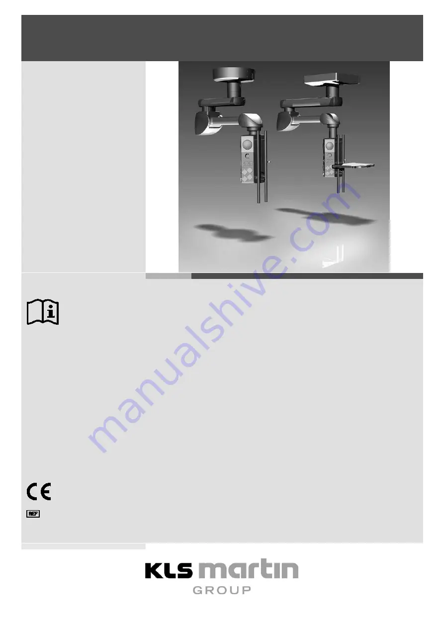
Suspension Arm Systems Independant
®
IDP 101 S air plus
Mounting Instructions
90-061-72-10
Revision 1
Date of Release: 2016-06
Page 1: ...English Suspension Arm Systems Independant IDP 101 S air plus Mounting Instructions 90 061 72 10 Revision 1 Date of Release 2016 06 ...
Page 2: ...inst improper handling of oxygen see section 4 2 4 Safe Handling of Oxygen page 29 Fire hazard Warns against improper handling of oxygen see section 4 2 4 Safe Handling of Oxygen page 29 Warning dangerous electric voltage Falling parts Warns against falling parts when standing under the suspension arm system while assembly disassembly work is being performed Snapping upwards of the spring arm Warn...
Page 3: ...ection 9 2 Technical Data page 100 Information on minimum and maximum atmospheric pressure for storage and transportation See section 9 2 Technical Data page 100 Information on minimum and maximum atmospheric humidity for storage and transportation See section 9 2 Technical Data page 100 Do not exceed the maximum load bearing capacity or payload Warns against sudden falling due to exceedance of th...
Page 4: ...Validity of this Document 18 2 2 Applicable Mounting Instructions 18 2 3 Symbols Used in this Document 20 3 Instructions for Safe Installation 21 3 1 Information on Device Identification 21 3 2 Required Installation Equipment 21 3 3 Requirements 21 3 3 1 Requirements for the Qualifications of the Service Technician 21 3 3 2 Requirements before Installation 21 3 3 3 Assembly Process 22 3 3 4 Unauth...
Page 5: ... Plate 51 7 3 4 Adjusting the Spring Arm Extension Arm on the Duo Interface Plate 53 7 4 Mounting the Console Tube on the Spring Arm 55 7 4 1 Overview of the Components in this Section 55 7 4 2 Mounting the Console Tube on the Spring Arm 56 7 5 Mounting Optional Equipment 57 7 5 1 Mounting the Extension Arm Light only for Retrofitting 57 7 6 Installing the Cables 58 7 6 1 Safety Notes 58 7 6 2 Con...
Page 6: ...84 7 9 8 Mounting the Upper Front Cover Panel on the Spring Arm 85 8 Adjustment Work 86 8 1 Safety Notice for Adjustment Work 86 8 2 Adjusting the Mechanical Brake for the M6 service head 86 8 3 Selecting the Load Bearing Capacity on the Spring Arm 87 8 4 Adjusting the Vertical Lift on the Spring Arm 91 8 5 Correcting the Vertical Alignment of the M6 Service Head 93 8 6 Swivel Stop on the Extensio...
Page 7: ...he base of the M6 service head as indirect light source in the OR SW 2 Spanner width 2 for Allen spanner ring spanner and flat spanner 1 Product Liability and Warranty 1 1 General Information We thank you for having decided to buy one of our products This product bears the CE marking which means that it satisfies the essential requirements laid down in the EC Directive concerning medical devices W...
Page 8: ...ndant 8 Revision 1 1 2 Scope of Delivery 1 2 1 Overview and Scope of Delivery for IDP101 S air plus Single Arm Fig 1 1 Overview of IDP 101 S air plus single arm Overview Interface plate Single Duo already installed Intermediate ceiling installed on site ...
Page 9: ...For assembly see section 7 9 Mounting the Canopy Cover Caps and Claddings page 75 Spring arm with ceiling tube pre assembled 1 spring arm Pre installed components 3 2 pneumatic pipes for pneumatic brake control 2 earthing cables 4 mm Included components 1 setscrew M16 DIN EN ISO 4028 2 ball stops Ø 12 7 mm 2 side panels front right left joint for spring arm 1 cover panel front joint for spring arm...
Page 10: ...IN EN ISO 4762 8 retaining washers S10 For pre assembly see section 7 2 Pre assembly Mounting the Longer Ceiling Tube on the Extension Arm page 43 Console tube 1 console tube customized length Pre installed components 1 earthing cable 4 mm Fastening elements for service head 8 countersunk screws with hexagon socket M10 x 20 mm 10 9 DIN EN ISO 10642 Fastening elements for installation of console tu...
Page 11: ... Systems Independant Revision 1 11 1 2 2 Overview and Scope of Delivery IDP 101 S air plus Dual Arm Fig 1 2 Overview IDP 101 S air plus dual arm Overview Interface plate Single Duo already installed Intermediate ceiling installed on site ...
Page 12: ...ge 75 Extension arm with spring arm and ceiling tube pre assembled 1 extension arm in the lengths 600 800 1 000 and 1 200 mm Pre installed components 3 pneumatic pipes for pneumatic brake control 3 earthing cables 4 mm 2 earthing cables if ceiling tube is not installed Included components 2 setscrews M16 DIN EN ISO 4028 2 ball stops Ø 12 7 mm 2 profile end caps for extension arm 2 side panels fron...
Page 13: ...O 4762 8 retaining washers S10 For pre assembly see section 7 2 Pre assembly Mounting the Longer Ceiling Tube on the Extension Arm page 43 Console tube 1 console tube customized length Pre installed components 1 earthing cable 4 mm Fastening elements for service head 8 countersunk screws with hexagon socket M10 x 20 mm 10 9 DIN EN ISO 10642 Fastening elements for installation of console tube to M6...
Page 14: ...ension arm light length 600 mm input voltage 12 VDC Pre installed components 3 closing plugs on the extension arm top 1 base support with LED and connection cable 1 electrical signal cables equipped with plugs on both sides 1 cover panel Extension arm light fastening elements 2 countersunk screws M4 x 16 mm with hexagon socket DIN EN ISO 10642 For retrofitting For assembly see section 7 5 1 Mounti...
Page 15: ...nly by instructed hygiene specialists The suspension arm system may be serviced only by the operator s technical specialists on the basis of the applicable instructions The operator may operate the device only if an on site functional test has previously been performed by Gebrüder Martin or a person authorized by Gebrüder Martin In addition a responsible person designated by the operator must have...
Page 16: ...rk If the repair is carried out by a person or firm specially authorized by Gebrüder Martin the operator of the product is required to obtain from the repairer a certificate with details about the nature and scope of the repair work done This certificate must show the date of the repair and the details of the person or firm carrying out the work and must be signed In all cases where a party other ...
Page 17: ...ical questions or questions concerning maintenance contracts or training courses please contact our Martin Service Center Tel 49 7461 706 343 Fax 49 7461 706 408 E Mail service klsmartin com NOTICE To answer your technical questions as efficiently as possible our service technicians require the serial number of the product Therefore please have this number at hand when contacting our hotline It is...
Page 18: ...e sure to heed all cautions warnings and danger notices Keep this document accessible to users at all times 2 1 Validity of this Document This document applies to Independant IDP 101 S air plus which is used as suspension arm system for the M6 service head This document is valid only in conjunction with Instructions for use of the M6 service head Instructions for use of the approved accessories fo...
Page 19: ... Arm Systems Independant Revision 1 19 Fig 2 2 Suspension arm system Part 02 Suspension arm system Part 03 M6 service head Fig 2 3 M6 service head Fig 2 4 Approved optional equipment Part 04 Approved equipment for the M6 service head ...
Page 20: ...ious injury Indicates a situation which if not avoided will result in death or serious injury WARNING Life hazard or serious injury Indicates a situation which if not avoided could result in death or serious injury CAUTION Risk of injury Indicates a situation which if not avoided could result in minor or moderate injury NOTICE Risk of material damage Indicates a situation which if not avoided coul...
Page 21: ...lings or walls Protective gloves Digital water level Torque spanner Multimeter Standard tool kit Telescopic magnet lifter set Working platform e g platform ladder according to national occupational safety regulations 3 3 Requirements 3 3 1 Requirements for the Qualifications of the Service Technician These Mounting Instructions are intended for trained technical qualified staff Installation and se...
Page 22: ...In case of unauthorized modifications or adjustments the manufacturer s warranty for the suspension arm system becomes void The manufacturer hereby excludes all liability for damage or injuries caused by unauthorized adjustments or modifications or as a result of the use of non original spare parts The use of parts that were not provided by the manufacturer or the manufacturer s representatives vo...
Page 23: ...n a technical training course conducted by Gebrüder Martin The authorization is granted for a limited time period 3 5 Standards and Guidelines The device meets the safety requirements of the following standards regulations and guidelines Abbreviation Designation MPG German Medical Devices Act Medizinproduktegesetz 93 42 EWG German Medical Devices Directive Medizinprodukterichtlinie IEC 60601 1 Ele...
Page 24: ...ed within the patient environment must be equipped with 2 means of patient protection MOPP according to IEC 60601 1 Any accessible parts located outside of the patient environment must be equipped with 2 means of operator protection MOOP according to IEC 60601 1 The figure shows the minimum extent of the patient environment in unrestricted surroundings Fig 3 1 Patient environment as defined in IEC...
Page 25: ...isplays the data for the power supply to the suspension arm system Load capacity The max load 30 60 kg data for example indicate the maximum allowable load bearing capacity of the extension arm Manufacturing date The manufacturing date of the suspension arm system is specified in digits 1 4 of the serial number SN The first two digits indicate the week of manufacture e g 11 calendar week 11 The tw...
Page 26: ...ension arm system or its components to loosen from the anchorage and fall down Do not exceed the maximum load bearing capacity of the suspension arm system and its components see section 9 2 Technical Data page 100 Do not hang or install any additional loads on the extension arm the M6 service head or end devices Collisions with other devices walls or ceilings can damage the suspension arm system ...
Page 27: ...hases can be simultaneously disconnected from the mains Disconnect the suspension arm system from the mains before beginning any assembly disassembly or adjustment work Disconnect all phases of the customer side power supply and secure it against reactivation Ensure that all the devices connected to the M6 service head are de energized WARNING Risk of injury from falling parts No persons may stay ...
Page 28: ...tective conductor in such a way that all of its phases can be simultaneously disconnected from the mains Disconnect the suspension arm system from the mains before beginning any maintenance work Disconnect all phases of the customer side power supply and secure it against reactivation Ensure that all the devices connected to the M6 service head are de energized CAUTION Risk of injury from damaged ...
Page 29: ... due to highly compressed oxygen Keep the oxygen and gas modules free of substances that contain oil grease or lubricants For cleaning do not use cleaning agents that contain oil grease or lubricants DANGER Danger to life from fire Escaping oxygen is a powerful oxidant and thereby greatly intensifies the combustion process Open fire glowing items or open light are not allowed when working with oxy...
Page 30: ...f a sticker the flawless function was confirmed by the operator during initial commissioning and documented in a declaration of handover Handover The following items must be complied with for the handover to the operator The suspension arm system and the M6 service head must be handed over to the operator in their inspected state The handover must be done in writing and confirmed by the operator T...
Page 31: ...how the values for the approved maximum load bearing capacity of the Single suspension arm system The load data of a Duo version can be added CAUTION Danger of injury due to the suspension arm system falling The required national safety factors must be included when calculating the maximum load data 6 1 Load Data for IDP 101 S air plus Fig 6 1 Load data for IDP 101 S air plus Spring arm length sin...
Page 32: ... air plus dual arm 6 2 Load Data for Suspension Arm Combinations Fig 6 4 Load data for suspension arm combinations The vertical weight forces and bending moments of the different suspension arm systems of Duo versions can be added Example IDP 101 S air plus spring arm 1 015 mm on ceiling mount combined with IDP 501 XL extension arm 1 200 1 000 mm Sum of weight forces 2 578 N 3 599 N 1 300 N 8 478 ...
Page 33: ...raw ceiling Single Duo Shortening the threaded bolts If Single Duo interface plates are mounted on a raw ceiling 6 Single version or 12 Duo version M16 x 330 mm threaded bolts will have to be shortened The Single Duo canopy with attachment to be mounted later fits closely to the raw ceiling and covers the flange of the ceiling tube If the canopy is 260 mm high shorten the 6 12 threaded bolts to 24...
Page 34: ...m to fall Fully screw in all shortened threaded bolts into the interface plate up to the end stop and on to the raw ceiling WARNING Danger of injury due to the suspension arm system falling and due not because of insufficient torque Insufficiently tightened fastening elements can cause the suspension arm system to fall Tighten all hexagonal nuts with a torque of 195 Nm Check they are securely in p...
Page 35: ...s to the interface plate to 150 mm Adjust the height position of the hexagonal nuts horizontally using a digital water level Place the ring washer external Ø 34 m Place the plastic insulation washer as shown in the illustration so that the ring washer is in the plastic insulation washer see arrow in the enlarged view in the illustration Fix plastic insulation washer using adhesive tape or rubber t...
Page 36: ...tes are mounted on a raw ceiling with intermediate ceiling 6 Single version or 12 Duo version M16 x 330 mm threaded bolts will have to be shortened The Single Duo canopy with attachment to be mounted later fits closely to the intermediate ceiling and covers the flange of the ceiling tube NOTICE Variable threaded bolt length The required length of the threaded bolts depends on the distance H raw ce...
Page 37: ... min 205 mm max 245 mm in case of doubt contact Gebrüder Martin Slightly deburr 6 12 threaded bolts so that a maximum thread engagement into the interface plate is ensured Mounting the threaded bolts on the interface plate Single Duo Fig 7 4 Mounting the threaded bolts on the interface plate Single Duo Attach 1 hexagonal nut M16 to each of the 6 12 threaded bolts M16 and use 1 spring washer for ea...
Page 38: ... interface plate up to the end stop and on to the raw ceiling WARNING Danger of injury due to the suspension arm system falling and due not because of insufficient torque Insufficiently tightened fastening elements can cause the suspension arm system to fall Tighten all hexagonal nuts with a torque of 195 Nm Check they are securely in place and that the distances between the shortened threaded bol...
Page 39: ...lculated distance L Adjust the height position of the hexagonal nuts horizontally using a digital water level Place the ring washer external Ø 34 mm Place the plastic insulation washer as shown in the illustration so that the ring washer is in the plastic insulation washer see arrow in the enlarged view in the illustration Fix plastic insulation washer using adhesive tape or rubber tape on the thr...
Page 40: ...nt Fig 7 6 Mounting the threaded bolts Single Duo Mounting the threaded bolts The 6 Single version or 12 Duo version threaded bolts M16 x 330 mm must protrude from the interface plate by a precise distance The Single Duo canopy with attachment to be mounted later fits closely to the intermediate ceiling and covers the flange of the ceiling tube ...
Page 41: ...nto the interface plate The threaded bolts must protrude by 220 mm Single Duo from the interface plate WARNING Danger of injury due to the suspension arm system falling and due not because of insufficient torque Insufficiently tightened fastening elements can cause the suspension arm system to fall Tighten all hexagonal nuts with a torque of 195 Nm Check they are securely in place and that the dis...
Page 42: ... nuts to the interface plate to 150 mm Adjust the height position of the hexagonal nuts horizontally using a digital water level Place the ring washer external Ø 34 mm Place the plastic insulation washer as shown in the illustration so that the ring washer is in the plastic insulation washer see arrow in the enlarged view in the illustration Fix plastic insulation washer using adhesive tape or rub...
Page 43: ... The ceiling tube shown in the illustration is mounted to the spring arm or the extension arm with spring arm For reasons of simplification the illustration shows the spring arm or extension arm with spring arm and without the pre installed cables The installation is described in the following sections and differs depending on the version Fig 7 8 Overview of the components in this section ...
Page 44: ...ng arm or extension arm with spring arm Attach 8 retaining washers S10 to 8 Allen cylinder screws M10 x 25 mm 8 8 DIN EN ISO 4762 At the position of the pre installed cable leave the threaded hole free and do not screw in cylinder screws Screw ceiling tube on the spring arm or the extension arm with spring arm using 7 cylinder screws and retaining washers Use an extension for tightening WARNING Da...
Page 45: ...k that the spring arm or the extension arm with spring arm is securely in place The ceiling tube must sit flush on the spring arm or extension arm with spring arm The 7 cylinder screws must be installed with retaining washers The 7 cylinder screws must be tightened with 40 Nm ...
Page 46: ...ng tube wall Place pre installed cable into the recess of the tension relief bracket Screw tension relief bracket on the spring arm or extension arm with spring arm using the cylinder screw and retaining washer Ensure that the cable is not pinched Establish the plug connection with the control cable and press the tension relief into the tension relief bracket Make sure the tension relief is secure...
Page 47: ...ystem from the factory the following earthing cable is already installed Attach 1 retaining washer S4 each above and below the ring cable lug of the supplied earthing cable 4 mm approx length 1 m Screw ring cable lug and retaining washers on the earthing point using 1 cylinder screw Tighten the cylinder screw Check protective resistor see section 10 Inspection Plan page 103 Continue assembly see s...
Page 48: ...s Section The spring arm or extension arm with spring arm is mounted to the threaded bolts of the interface plate For reasons of simplification the illustration shows the spring arm or extension arm with spring arm without pre installed cables The installation is described in the following sections and is the same for all components Fig 7 12 Overview of the components in this section ...
Page 49: ...is mounted to the threaded bolts Additional components pre mounted on the flange e g spring arm extension arm or cables are not illustrated Fig 7 13 Mounting the ceiling tube Single Duo WARNING Danger of injury by trapped limbs or from collisions Limbs may be trapped during assembly work Components of the suspension arm system may cause collisions During the installation be particularly careful ...
Page 50: ...me height Mount the flanges in a way that the chamfered surfaces point towards each other Insert flange of the ceiling tube with spring arm or extension arm with spring arm into the 6 threaded bolts of the interface plate Remove the previously attached adhesive tape or rubber tape from the threaded bolts For each threaded bolt attach 1 plastic insulation washer as per the illustration in a way tha...
Page 51: ...stem is securely positioned WARNING Danger of injury due to the suspension arm system falling and due not because of insufficient torque Insufficiently tightened fastening elements can cause the suspension arm system to fall Tighten all hexagonal nuts M16 with a torque of 100 Nm NOTICE Possible destruction of the cables in the extension arm The extension arm is supplied ex works without a swivel s...
Page 52: ... water level diagonally to the length of the spring arm extension arm on the spring arm extension arm near the flange Rotate spring arm extension arm by 90 in different directions and check the horizontal alignment The horizontal deviation may not exceed 0 2 In case of deviations of more than 0 2 the spring arm extension arm must be aligned again according to the installation steps described above...
Page 53: ...em is securely positioned WARNING Danger of injury due to the suspension arm system falling and due not because of insufficient torque Insufficiently tightened fastening elements can cause the suspension arm system to fall Tighten all hexagonal nuts M16 with a torque of 100 Nm NOTICE Possible destruction of the cables in the extension arm The extension arm is supplied ex works without a swivel sto...
Page 54: ... Fig 7 16 Adjusting the spring arm extension arm on the Duo interface plate Check the horizontal alignment of the spring arm extension arm Place a digital water level diagonally to the length of the spring arm extension arm on the spring arm extension arm near the flange Rotate spring arm extension arm by 90 in different directions and check the horizontal alignment The horizontal deviation may no...
Page 55: ...al nuts must be tightened with 100 Nm 7 4 Mounting the Console Tube on the Spring Arm 7 4 1 Overview of the Components in this Section The console tube shown in the illustration is mounted to the spring arm or extension arm with spring arm For reasons of simplification the illustration shows the spring arm or extension arm with spring arm without cables The installation is described in the followi...
Page 56: ...ith the stop on the right side If the M6 service head is to be swiveled to the right in clockwise direction Install the console tube with the stop on the left side Fig 7 19 Mounting the console tube on the spring arm Screw the console tube on the spring arm using 8 countersunk screws with hexagon socket M10 x 25 mm 10 9 DIN EN ISO 10642 WARNING Danger of injury due to the suspension arm system fal...
Page 57: ...g arm without cables Remove 3 closing plugs not illustrated from the top of the extension arm and dispose of appropriately Feed the connection cable on the base support with LED through the mounting opening in the extension arm without bending it Place cover panel on the base support with LED and screw on using 2 countersunk screws M4 x 16 mm DIN EN ISO 10642 Fig 7 20 Mounting the extension arm li...
Page 58: ...hboring live parts WARNING Danger of injury due to damaged supply cables power cables gas and compressed air tubes Damaged supply cables and supply tubes can result in electric current entering the suspension arm system 230 VAC or 120 VAC Moreover supply gases could be emitted All leads and tubes must be checked for damage and be drawn in carefully without any overlapping loops or twists Lay out c...
Page 59: ...bent brake pipes The supply pressure of the air supply ducts at the installation site must be in a range from 4 to 6 bar The optimum operating pressure is 5 bar 7 6 2 Connecting the Cables on the Extension Arm with Spring Arm Dual Arm to the M6 Service Head Observe the safety notes see section 7 6 1 Safety Notes page 58 Fig 7 21 Connecting the cables on the extension arm with spring arm dual arm t...
Page 60: ...ng arm above the swivel axis swivel joint and lead it out of the mounting opening in the bearing block of the spring arm Lay the power cable through the extension arm and towards the interface plate 7 6 3 Laying and Connecting the Pneumatic Brake Pipes Observe the safety notes see section 7 6 1 Safety Notes page 58 Fig 7 22 Laying and connecting the pneumatic brake pipes ...
Page 61: ...rake pipes Insert the pneumatic brake lines into the mounting opening in the in the bearing support of the spring arm and lay them above the swivel axis swivel joint Plug the air supply hose black marking onto the plug connector black marking Plug the brake pipe green marking onto the plug connector green marking Plug the brake pipe blue marking onto the plug connector blue marking Connect the air...
Page 62: ...xtension arm lighting M6 service head Cbl extension arm lighting distr cons 3 000 _ Insert the extension arm lighting cable into the mounting opening in the in the bearing support of the spring arm and lay them above the swivel axis swivel joint Establish a plug connection between cable and the extension arm lighting using the extension cable included in the scope of delivery Lead the extension ca...
Page 63: ...connected Lay out the earthing cables in the direction of the arrow as seen in the illustration connect them and feed them to the interface plate if applicable Insert the grounding cables into the mounting opening in the bearing block of the spring arm and lay them above the swivel axis swivel joint Lead the installed grounding cable of the flange on the ceiling tube to the interface plate Lay the...
Page 64: ...e g for nurse call or telephony must be laid separately through the suspension arm system Carefully lay the supply cables and supply tubes through the suspension arm system to the interface plate Lay the supply cables and supply tubes through the spring arm above the swivel axis swivel joint and lead them into the mounting opening in the bearing block of the spring arm Then readjust the M6 service...
Page 65: ... service head The power cables pneumatic pipes earthing and control cables as well as the gas hoses are pre installed in the M6 Service Head and must be routed through the pendant system Laying the power cable Lay the power cable laid in a spiral coiled tube if required through the spring arm above the swivel axis swivel joint and lead it out of the mounting opening in the bearing block of the spr...
Page 66: ...c Brake Pipes Observe the safety notes see section 7 6 1 Safety Notes page 58 Fig 7 27 Laying and connecting the pneumatic brake pipes The pneumatic brake pipes are pre assembled in the suspension arm system and plugged onto the brake connecting point The pneumatic brake pipes are possibly laid in a spiral tube ...
Page 67: ...mounting opening in the in the bearing support of the spring arm and lay them above the swivel axis swivel joint Plug the air supply hose black marking onto the plug connector black marking Plug the brake pipe green marking onto the plug connector green marking Plug the brake pipe blue marking onto the plug connector blue marking Connect the air supply hose and the 2 brake pipes to the plug connec...
Page 68: ...ng cables in the direction of the arrow as seen in the illustration connect them and feed them to the interface plate if applicable Insert the grounding cables into the mounting opening in the bearing block of the spring arm and lay them above the swivel axis swivel joint Lead the installed grounding cable of the flange on the ceiling tube to the interface plate Lay the grounding cables from the M...
Page 69: ...ll or telephony must be laid separately through the suspension arm system Carefully lay the supply cables and supply tubes through the suspension arm system to the interface plate Lay the supply cables and supply tubes through the spring arm above the swivel axis swivel joint and lead them into the mounting opening in the bearing block of the spring arm Then readjust the M6 service head without pu...
Page 70: ...must be checked for tightness pressure flow and contamination The check of gas types must be documented see section 7 8 1 Gas Type Check M6 Service Head only page 74 After repair or modification of the gas system a check must be performed WARNING Risk of death by electrocution Touching live parts can cause life threatening electric shock Motor controlled movable components of the unit can cause in...
Page 71: ...Lay out cables and tubes in the suspension arm system in such a manner that they are not subjected to tension in any position Cables and tubes must be fed directly upwards out of the flange to avoid possible damage e g scuffing the coating etc and to ensure that all cables and tubes can rotate freely Excess lengths of cable or tube must never be placed in the M6 service head or on the flanges they...
Page 72: ... the gas supply cable remove closing plug and slide onto the corresponding gas supply connection If required a maximum of 3 gas supply tubes and a maximum of 2 vacuum tubes may be connected to a gas valve using Y pieces Squeeze in the hose clamps and make sure they are safely in place Connect and secure anesthesia suction system and air spring exhaust air tubes Perform gas type check see section 7...
Page 73: ...2 5 mm and 10 mm in length Feed the earthing cables through the tension relief and connect them to the series terminal 4 mm or 10 mm on the earthing terminal unit on the interface plate Ensure that the earthing cables are safely in place in the tension relief All earthing cables must sit securely in the tension relief 7 7 4 Connecting the Power Cables Fig 7 32 Connecting the power cables Single an...
Page 74: ...e spring arm 7 8 Checks 7 8 1 Gas Type Check M6 Service Head only NOTICE The gas type check must be performed and documented by the supplier of the central gas system or a qualified specialized company The following checks must be performed Connections and labeling acc to DIN EN ISO 91701 or DIN EN ISO 91702 Leakage acc to DIN EN ISO 11197 Obstruction acc to DIN EN ISO 73961 or DIN EN ISO 73962 So...
Page 75: ...that the canopy halves in the connection are aligned with the intermediate ceiling prefabricated ceiling If there is an interface plate on the raw ceiling shorten the threaded bolts accordingly WARNING Danger of injury due to the suspension arm system falling Insufficiently tightened fastening elements can cause the suspension arm system to fall Tighten 4 or 6 hexagonal nuts with a torque of 46 Nm...
Page 76: ...the canopy halves sit flush on the intermediate ceiling prefabricated ceiling If required re adjust the 6 threaded bolts see section Preparing to mount the canopy page 75 Attach profile strip not illustrated to the second canopy half and insert into the first canopy half so that one is inside the other Place the second canopy half on the threaded bolts and screw on and tighten 3 cladding screws Fi...
Page 77: ...s in the connection are aligned with the intermediate ceiling prefabricated ceiling If there is an interface plate on the raw ceiling shorten the threaded bolts accordingly WARNING Danger of injury due to the suspension arm system falling Insufficiently tightened fastening elements can cause the suspension arm system to fall Tighten 4 hexagonal nuts with a torque of 46 Nm Fig 7 35 Preparing to mou...
Page 78: ...re adjust the 4 threaded bolts see section Preparing to mount the canopy page 77 Attach profile strip not illustrated to the second canopy half and insert into the first canopy half so that one is inside the other Place the second canopy half on the threaded bolts and screw on and tighten 2 cladding screws Fig 7 36 Mounting the canopy halves Screw 1 self tapping screw each on the 2 flaps on the op...
Page 79: ...rm end in a manner that the hold down device sits in the opening Slide the cover cap on the extension arm with spring arm up to the end stop so that the latch snaps into the groove Ensure that the power supply unit and the internal cables in the extension arm with spring arm are not damaged If the installation has been performed correctly the cover cap cannot be pulled off the extension arm with s...
Page 80: ...lat narrow screwdriver between the cover cap and the extension arm with spring arm and carefully lever the latch out of the groove Avoid damaging the paint on the extension arm and the latch and make sure that the cover cap is not damaged or bent Pull cover cap backwards until the hold down device is no longer gripping it and the cover cap can be moved freely Do not jam or remove the cover cap wit...
Page 81: ...ng the Plates on the Spring Arm The illustration shows the spring arm The mounting process for the extension arm with spring arm is identical For reasons of simplification the illustration shows the spring arm without cables or main board Fig 7 39 Mounting the plates on the spring arm ...
Page 82: ...n the Spring Arm The illustration shows the spring arm The mounting process for the extension arm with spring arm is identical For reasons of simplification the illustration shows the spring arm without cables Attach the first side cladding and insert 3 plastic pins into the holes on the spring arm The plate must snap into the guide of the side cladding Attach the second side cladding and insert 3...
Page 83: ...shows the spring arm without cables or main board Stop the cover panel in the illustrated setting angle Insert the joint of the lower rear cover panel in the 2 holders of the upper side claddings Fold the cover panel upwards until the 2 latches engage Make sure the cover panel is safely in place The guides of the cover panel must sit in the side claddings The cover panel must butt against the side...
Page 84: ...snap into the guide not illustrated of the side cladding Insert the side cladding into the holder on the front of the right side cladding guide it to the spring arm and insert 2 plastic pins into the holes on the spring arm The plate must snap into the guide not illustrated of the side cladding Carefully guide 2 flaps on the bottom into each other and connect with each other Make sure the side cla...
Page 85: ...ut cables Position the cover panel from the top and insert one of the two axes into the holder of the side cladding Carefully pull apart the upper cover panel and insert the second axis into the holder of the side cladding Fold the cover panel downwards until the 2 latches engage Make sure the cover panel is safely in place The guides of the cover panel must sit in the side claddings The cover pan...
Page 86: ...ustment work turn off the suspension arm system and secure it against accidental reactivation Ensure that all the devices connected to the M6 service head are disconnected from the power supply 8 2 Adjusting the Mechanical Brake for the M6 service head Observe the safety notice see section 8 1 Safety Notice for Adjustment Work page 86 In all versions the mechanical brake friction brake on the cons...
Page 87: ...Load Bearing Capacity on the Spring Arm The spring arm is equipped with 1 or 2 springs These springs balance the weight of the M6 service head with the end device e g TFT monitor or medical device Select the load bearing capacity of the spring arm so that the spring arm with the M6 service head and the end device latches in every position independently If the spring arms does not remain in the des...
Page 88: ...ring arm for simplification without installed cables The adjustment is identical for all versions Observe the safety notice see section 8 1 Safety Notice for Adjustment Work page 86 Successively press a suitable screwdriver into the 2 openings and unlock the 2 latches Fold the lower cover on the rear downwards Fig 8 2 Opening the lower cover panel on the rear ...
Page 89: ...e spring arm to approx 10 above the horizontal position 0 position to relieve the burden on the adjustment screw If the spring arm moves downwards the load bearing capacity is too low Turn hexagon spanner to the left counterclockwise as shown in the illustration If the spring arm moves upwards the load bearing capacity is too high Turn hexagon spanner to the right clockwise as shown in the illustr...
Page 90: ... during operation over time The spring arm will then fail to remain in the set position Tighten the cylinder screw with a torque of 12 Nm Closing the lower cover panel on the rear Fold the lower cover panel on the rear upwards until the 2 latches engage Make sure the cover panel is safely in place The guides not shown of the cover must be engaged in the side claddings The cover panel must butt aga...
Page 91: ...river into the 2 openings and unlock the 2 latches Fold the upper cover on the front upwards until it latches Adjusting the Vertical Lift Tools to be used Hexagon spanner SW 10 and ring spanner SW 18 Loosen hexagonal nut M12 ISO 4035 and turn it back Insert hexagon spanner into adjustment screw To reduce the vertical lift Turn hexagon spanner to the left counterclockwise as shown in the illustrati...
Page 92: ... time The spring arm can then collide with the ceiling or another suspension arm system arm system Tighten the hexagon nut with a torque of 30 Nm Closing upper casing on the front Fold the upper cover on the front downwards until the 2 latches engage Make sure the cover panel is safely in place The guides not shown of the cover must be engaged in the side claddings The cover panel must butt agains...
Page 93: ... into the 2 openings and unlock the 2 latches Fold the lower casing on the rear downwards Correcting the vertical alignment Tools to be used Hexagon spanner SW 4 and flat spanner SW 36 Loosen setscrew M4 DIN 914 Place the flat spanner on the hexagonal bolt The indicator screw points downwards do not loosen this screw To lower the shelf Turn hexagonal bolt so that the indicator screw points to the ...
Page 94: ...el Stop on the Extension Arm and Spring Arm The extension arm and the spring arm must be equipped with at least one swivel stop that prevents destruction of the internally laid cables Installing 1 ball stop reduces the maximum range of rotation to a maximum value of 340 Installing 2 ball stops further reduces the range of rotation by steps of 15 WARNING Risk of death by electrocution At least one ...
Page 95: ...s fully locked in one of the mounting fixtures the extension arm or spring arm can be rotated Otherwise it is blocked and the ball stop must be pressed into one of the mounting fixtures using a screwdriver while carefully rotating the extension arm or spring arm Turn the extension arm or spring arm to the desired second stop position and insert 1 additional ball stop into the threaded hole Slightl...
Page 96: ...ing elements can lead to failure of the swivel stop Moreover supply cables could loosen Tighten the M16 setscrew to 40 Nm Check that the swivel stop is working properly The range of rotation of the extension arm or spring arm must be limited to less than 360 To modify an installed ball stop see section 8 6 2 Removing the Swivel Stop page 97 ...
Page 97: ...s visible in the threaded hole Use a telescopic magnet pick up tool set to guide 1 ball stop out of the threaded hole and store it in a safe place WARNING Risk of death by electrocution At least one ball stop must be correctly installed to prevent twisting of the internal supply lines The single installed ball stop prevents twisting Install the swivel stop immediately Install at least 1 ball stop ...
Page 98: ...he following dimensional drawings can differ from the individually configured ceiling installation The round canopy can be installed only with the round interface panel The square 700 mm 700 mm canopy can be installed solely with the square interface panel 9 1 1 Spring Arm IDP 101 S air plus Single Arm with M6 Service Head ...
Page 99: ...Mounting Instructions Suspension Arm Systems Independant Revision 1 99 9 1 2 Spring Arm IDP 101 S air plus Dual Arm with M6 Service Head ...
Page 100: ... 800 mm 105 kg Extension arm 1 000 mm 108 kg Extension arm 1 200 mm 111 kg Bearing unit console tube 5 kg 8 kg m Ceiling tube for extension arm Flange Steel tube 6 kg 24 kg m 9 2 2 Maximum Load Bearing Capacity Designation Max load bearing capacity Spring arm length 1 015 mm 180 kg IDP 101 S air plus with spring arm Extension arm 600 mm 180 kg Extension arm 800 mm 170 kg Extension arm 1 000 mm 150...
Page 101: ...ted in series to 24 VDC 12 VDC Sound pressure level A level of 65 db A EN ISO 3746 is not exceeded Manual forces when the electromagnetic brake is released depending on position and payload 3 5 40 Nm Protection class acc to IEC 60601 1 I IP classification as per IEC 60529 IP 20 Approvals of the standard design Recognized NRTL component Ambient conditions Storage and transportation 25 C to 70 C 13 ...
Page 102: ...mbination of any other Gebrüder Martin product with the suspension arm system must be confirmed by Gebrüder Martin A new conformity evaluation may have to be created The suspension arm system can be equipped with adaptions and end devices by other manufacturers The maximum load bearing capacity must be noted here to prevent dangerous overloading which could lead to damage or collapse of the suspen...
Page 103: ... present and positioned correctly All rating plates and labels are provided and clearly legible All the fastening screws of the canopy are provided and firmly installed Function check Perform annually Not OK OK The suspension arm system is securely positioned adjust the swivel stops if necessary At least 1 swivel stop is set at every pivot point and is correctly installed and effective The extensi...
Page 104: ...uns smoothly and is adequately greased regrease with Gleitmo 810 if required additionally for IDP 101 S Not OK OK Load compensation spring force correct readjust as needed Comments The work listed above was performed including the required adjustment work and safety inspection Date Name in block letters Signature Stamp Any damaged deformed or missing components should be replaced by way of precaut...
Page 105: ...sal of the Device In designing the device we tried to avoid using composite materials wherever possible This allows a high degree of recycling We therefore offer to take the device back for proper disposal and recycling Be sure to observe your national local rules and regulations governing disposal Marking of electric and electronic equipment in accordance with Directive 2002 96 EC WEEE Directive ...
Page 106: ... 6251 china klsmartin com Martin Nederland Marned B V 1270 AG Huizen The Netherlands Tel 31 35 523 45 38 nederland klsmartin com KLS Martin L P Jacksonville Fl 32246 USA Tel 1 904 641 77 46 usa klsmartin com KLS Martin Asia Snd Bhd 14100 Simpang Ambat Penang Malaysia Tel 604 505 7838 malaysia klsmartin com Gebrüder Martin GmbH Co KG Representative Office Dubai United Arab Emirates Tel 971 4 454 16...