


44
EVO-S COMPACT
COMPACT AIR HANDLING UNIT
OPERATION AND MAINTENANCE MANUAL
4.3 WH Water Heaters
A standard water heater consists of a galvanized sheet
steel housing and a CuAl package with copper tubes and
aluminium fins. The collectors and stubs are made of cop-
per or steel.
The exchanger is equipped with drain and venting plugs.
During installation of the hydraulic system, it is recommen-
ded to supplement the pipes leading to the exchanger
with drain and vent valves.
When connecting the heaters to the supply system please
follow the recommendations of section 4.5.1.
Dismantling the water exchanger involves unscrewing the
supply and return pipes, dismantling the casing panel from
the operating side and possibly removing the installation
from the section area. The exchanger can be removed.
In case of access to the exchanger section, also from the
opposite side of the control panel’s operation, the pipes
are to be unscrewed, the rear cover has to be removed and
the exchanger can be pulled out.
Vertical elements of the exchanger casing that come into
contact with the unit casing are equipped with a self-adhe-
sive seal. The anti-freeze thermostat is delivered together
with the exchanger and is mounted on it beforehand.
4.4 EH Electric Heaters
The electric heaters installed in the units can be single or
multi-stage with different power distribution for each stage.
Radiant heaters with a large heat transfer surface are used in
the heaters. The heaters are factory connected to a terminal
strip.
A gland is mounted in the heater block cover to guide the
heater supply line. A diagram of heater connection to the
terminal strip is glued to the housing.
Electric heaters are equipped with a thermal switch protec-
ting the device against overheating, in case of air flow loss.
Such a switch, which has normally closed contacts, should
be included in the design of the control system.
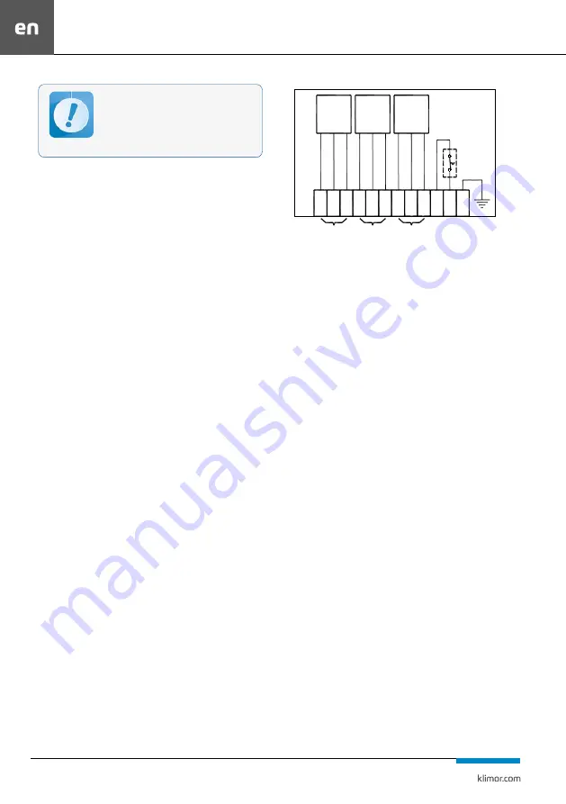
Fig. 30
Example of heater and thermostat connection to a terminal strip in a three-stage
heater
4.4.1 Operation of the electric heater
The electric heater should be kept clean. Dust settling on the
heating elements hampers heat output, and as a result may
cause burnout of the heating elements and a fire hazard. The
condition of the heating elements should be checked every
four months. They should be cleaned with a vacuum cleaner
with a soft suction nozzle on the side of air inlet or blown
through with compressed air. Wet cleaning is not allowed.
4.5 WC and DX Cooler
The task of water and glycol coolers and direct evaporation
of DX is to reduce the air temperature to that required by
the design data.
A standard cooler consists of a galvanized sheet steel casing
and a CuAl package with copper tubes and aluminium fins.
The collectors and stubs are made of copper or steel.
The water and glycol exchanger is equipped with drain and
vent plugs. During installation of the hydraulic system, it is
recommended to supplement the pipes leading to the ex-
changer with drain and vent valves. When connecting the
coolers to the supply system, it is necessary to follow the re-
commendations from chapter 4.5.1. Behind the cooler there
is a condenser for catching water drops.
For the sectional coolers, in the double exchanger version,
the condenser is mounted behind the second cooler.
Under the cooling block there is a drip tray with a stub for
condensate drainage. The trap is supplied.
4.5.1 Cooler and heater exchanger connections
Water heaters and coolers
Exchangers should be connected in such a way as to prevent
stresses that may cause mechanical damage and leaks. To this
end we recommend appropriate compensation of the supply
and return pipeline mitigating longitudinal expansion of the
pipes. When screwing the supply and return pipes to the ex-
changer stubs, use a lock key to hold the stub pipe.
Separators mounted between the filters are not
included in the service equipment and cannot be
replaced with new ones. Therefore, when repla-
cing the filters, they must be secured for reuse.
Lack of separators will result in bypass air flow
bypassing the filters.
T T N
TZ
III
II
S E KC JA
S E KC JA
I
S E KC JA
1 2 3 4 5 6 7 8 9
3x400V
stopieñ I
stopieñ II
3x400V
3x400V
stopieñ III
SECTION
I
level I
level II
level III
SECTION
II
SECTION
III
Summary of Contents for EVO-S COMPACT
Page 2: ...SERWIS SERVICE 4858 7839950 51 48 510098081 serwis klimor com...
Page 30: ...SERWIS SERVICE 48 587839950 51 48 510098081 seriws klimor com...
Page 58: ...SERWIS SERVICE 48 587839950 51 48 510098081 serwis klimor com...
Page 59: ...EVO S COMPACT KLIMOR...
Page 65: ...63 7 8 9 10 11 50 DN40 11...
Page 67: ...65 b 200x200 16 17 16 17 c 200x200 300x200 18 18 3 2 2 EVO 2000 5100 5610 19 13 M12 M12 M12 19...
Page 68: ...66 EVO S CO CT 2900 a 50 20 b 150 21 c 22 2900 b c...
Page 75: ...73 31 32 30 10 20 1 100 C 2 3 32 4 5 DX 0 03 4 5 2 12 12 4 5 3 DX...
Page 76: ...74 EVO S CO CT CHA 4 5 4 34 4 5 5 35 4 5 6 DX 36 DX MHA...
Page 82: ...80 EVO S CO CT 8 19 1 2 3 DX 4 5 6...
Page 84: ...82 EVO S CO CT c IP54 d e 41 1 1 42 f A IP65...
Page 85: ...83 11...
Page 86: ...SERWIS SERVICE 48 587839950 51 48 510098081 serwis klimor com...
Page 87: ......