background image

6482-901-01 Rev. A / August 2012

Return to 

Section Topics

3-5

Model 6482 Dual-Channel Picoammeter / Voltage Source Reference Manual

Section 3: Basic Operation

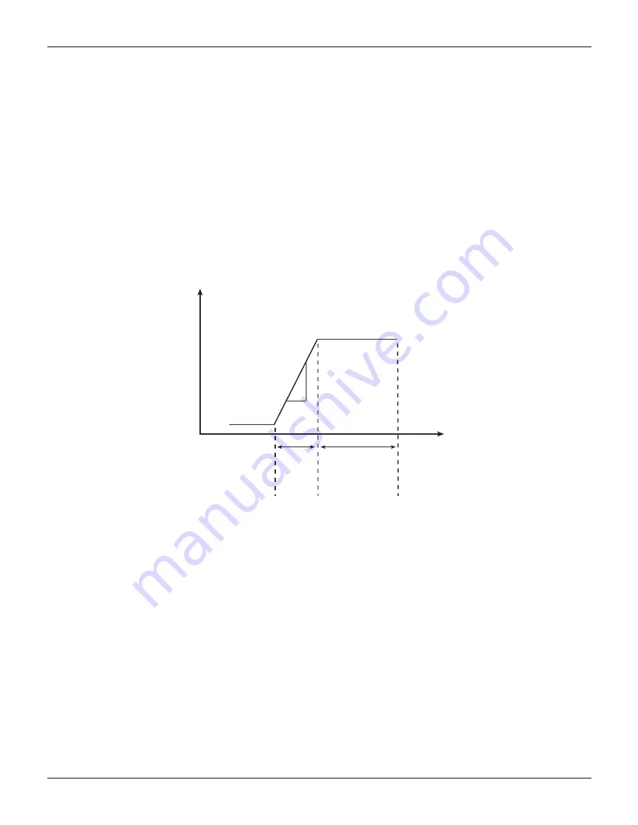
Output slew time

Figure 3-2

 demonstrates the effect of output slew time on overall settling. Total time after changing 

the source value before accurate measurements can be taken includes both the slew time and the 
measure circuit settling time.

NOTE

When not performing a sweep, the output slew time is not part of the automatic source 
delay. Therefore, for best accuracy when turning the output on or changing the voltage 
source value, allow a delay of 3.07 ms/V (milliseconds per volt) of output change before 
triggering a reading. This delay can be programmed by setting the trigger delay (see 

Section 8

“Front-panel operation of the trigger model”

). Also, while the output is slewing, 

the compliance status bit for the channel will be set (

Section 13

“Status Structure”

). You 

can poll the compliance bit to determine when the programmed source value is reached 
and an accurate reading can be taken.

Figure 3-2

Output slew time

Manual delay

Manual delay for each channel can be set from 0000.00000 to 9999.99800 seconds. Manually 
setting the delay disables autodelay.

Front panel source delay

NOTE

The delay period is the same for both sources. If you change the delay on one channel, 
the delay period on the other source will change to the same value.

To set the manual source delay from the front panel:

1. Press the 

CONFIG

 key, and then press the 

SRC1

 or 

SRC2

 key.

2. Select 

DELAY

 from the displayed choices, and then press the 

ENTER

 key.

3. Enter your delay value, and then press the 

ENTER

 key.

To set the automatic source delay state from the front panel:

1. Press the 

CONFIG

 key, and then the 

SRC1

 or 

SRC2

 key.

3.07ms/V

Output

settled

Accurate readings

can be taken

Output

slew

Measurement

circuit

settling

Source

value

changed

Time

Volts

Summary of Contents for 6482

Page 1: ...www keithley com A G R E A T E R M E A S U R E O F C O N F I D E N C E Model 6482 Dual Channel Picoammeter Voltage Source Reference Manual 6482 901 01 Rev A August 2012...

Page 2: ...Model 6482 Dual Channel Picoammeter Voltage Source Reference Manual 2007 2012 Keithley Instruments Inc All rights reserved Cleveland Ohio U S A 6482 901 01 Rev A August 2012 Document Number...

Page 3: ......

Page 4: ...replacement 1 9 Display 1 10 Display format 1 10 DISPLAY CHANNEL SELECT key 1 10 DISPLAY TOGGLE key 1 10 Status and error messages 1 10 Disabling the front panel display 1 10 Remote display programmi...

Page 5: ...e 3 9 Using the analog outputs 3 11 4 Range Digits Speed and Filters 4 1 Range and digits 4 2 Measurement range 4 2 Digits 4 3 Remote range and digits programming 4 4 Range and digits programming exam...

Page 6: ...ts 8 6 Operation summary 8 6 Trigger link 8 6 Input trigger requirements 8 7 Output trigger specifications 8 7 External triggering example 8 8 Configuring triggering 8 12 CONFIGURE TRIGGER menu 8 12 R...

Page 7: ...e OUTPUT menu 11 4 Remote output configuration 11 4 Output configuration commands 11 4 Output configuration programming example 11 5 12 Remote Operations 12 1 Remote versus local operation 12 2 Local...

Page 8: ...ter bit descriptions 13 9 Condition registers 13 15 Event registers 13 15 Event enable registers 13 15 Queues 13 16 Output queue 13 17 Error queue 13 17 14 Common Commands 14 1 Command summary 14 2 Co...

Page 9: ...OUTPut subsystem 16 34 Turn source on or off 16 34 Output enable control 16 35 SENSe subsystem 16 35 Select measurement range 16 35 Select autorange 16 36 Set measurement speed 16 37 Configure and co...

Page 10: ...Calibration adjustment cycle 17 14 Recommended calibration adjustment equipment 17 14 Calibration menu 17 15 Unlocking calibration 17 15 Unlocking calibration from the front panel 17 15 Unlocking cali...

Page 11: ...sequences C 10 IEEE command groups C 12 Interface function codes C 12 D Measurement Considerations D 1 Low current measurements D 2 Leakage currents D 2 Noise and source impedance D 2 Generated curren...

Page 12: ...ith electrical signals that are rated Measurement Category I and Measurement Category II as described in the International Electrotechnical Commission IEC Standard IEC 60664 Most measurement control a...

Page 13: ...k of electric shock Use standard safety precautions to avoid personal contact with these voltages The symbol on an instrument shows that the surface may be hot Avoid personal contact to prevent burns...

Page 14: ...Started In this section Topic Page Introduction 1 2 General information 1 2 Product overview 1 4 Specifications 1 5 Front and rear panel familiarization 1 5 Power up 1 8 Display 1 10 Default settings...

Page 15: ...are available on many products These valuable contracts protect you from unbudgeted service expenses and provide additional years of protection at a fraction of the price of a repair Extended warrant...

Page 16: ...of the Model 6482 Write ATTENTION REPAIR DEPARTMENT and the RMA number o n the shipping label Options and accessories The following options and accessories are available from Keithley for use with th...

Page 17: ...rack Model 4288 2 side by side rack mount kit Mounts two instruments Models 428 PROG 2000 2001 2002 2010 2015 2016 2400 2410 2420 2430 2500 2510 6430 6482 6485 6517A 7001 next to each other in a stan...

Page 18: ...and offset functions Reading and setup storage Up to 3000 point buffer on each channel that can contain up to 5 digit readings and seven setups five user defaults factory default RST default that can...

Page 19: ...ger a measurement from the front panel SWEEP Start a configured sweep DIGITS Change the number of digits of display resolution SPEED Change measurement speed by selecting accuracy or specifying NPLC S...

Page 20: ...nd CHANNEL 2 analog outputs Triaxial connector terminals Center conductor Analog output HI Inner shield Analog output LO analog common Outer shield Chassis ground VOLTAGE SOURCE connectors OUTPUT CHAN...

Page 21: ...If the voltage setting is not correct change it as described in Section 18 Line power connection Perform the following steps to connect the Model 6482 to line power and turn it on 1 Before plugging in...

Page 22: ...frequency setting 50 Hz or 60 Hz does not match the power line frequency in your area noisy measurement readings will result and accuracy may be affected You can manually set the line frequency from...

Page 23: ...ous states of operation as covered previously in Front panel summary DISPLAY CHANNEL SELECT key The CHANNEL SELECT key toggles between the channel 1 and channel 2 measurements on the display s left si...

Page 24: ...ote that with this option the display will disable while performing a sweep Sweep readings are automatically stored in the buffer Remote display programming The display can be controlled by various SC...

Page 25: ...key select SAVESETUP and then press the ENTER key 2 From the SAVESETUP MENU select RESTORE and then press the ENTER key 3 Using the EDIT or RANGE or keys select the setup position 0 4 to restore and t...

Page 26: ...rance Median filter rank state GPIB address Ground connect Limit tests H W limits 1 and 2 Control Fail mode S W limits 3 to 6 Control Feed Math function and units M factor gain B factor slope State Nu...

Page 27: ...layer Event Count Timer Input line Output trigger Trigger layer Event Count Timer Input line Output triggers Delay Voltage bias sources Amplitude Range Mode Speed Sweep Start Stop Step Direction Swee...

Page 28: ...Return the Model 6482 to setup saved in memory Select the power on default setup Powers on to BENCH defaults Powers on to GPIB defaults Powers on to user setup Returns instrument to BENCH or GPIB def...

Page 29: ...of cursor position NOTE You can clear a parameter value by placing the cursor on it and pressing the 0000 MENU key Boolean selections such as ON OFF and HIGH LOW are toggled by placing the cursor on t...

Page 30: ...ys to edit voltage bias values SRC1 or SRC2 selects the channel 1 Src1 or channel 2 Src2 source display field on the lower line for editing A blinking cursor will appear in the field to be edited If n...

Page 31: ...nking cursor on the digit to be changed then increment or decrement the value with the EDIT and keys Note that the source value will be updated immediately you do not need to press the ENTER key to co...

Page 32: ...M and B values Electrical power V I measurement Configure ratio function MSR1 MSR2 function MSR2 MSR1 function Configure delta function MSR1 MSR2 function MSR2 MSR1 function Table 1 5 Source configura...

Page 33: ...nced filter Enable advance filter set noise tolerance Select median rank 0 to 5 Program upper range limit Program lower range limit Table 1 7 Limit configuration menu Configuration menu item Descripti...

Page 34: ...nt detection once Never bypass event detection When SOT is pulsed low Bypass event detection once Never bypass event detection When SOT line is pulsed high Bypass event detection once Never bypass eve...

Page 35: ...re sweeps of the selected channel Select sweep type Disable sweep Staircase sweep program START STOP STEP Logarithmic sweep program START STOP POINTS Custom sweep program parameters Program number of...

Page 36: ...DISPLAY CHANNEL SELECT CONFIGURE DISPLAY NOW NEVER SWEEP STORE Configure output Enable or disable auto off mode Keep output on Turn output off after each measurement After each measurement When trigge...

Page 37: ...This page left blank intentionally 1 24 Return to Section Topics 6482 901 01 Rev A August 2012 Section 1 Getting Started Model 6482 Dual Channel Picoammeter Voltage Source Reference Manual...

Page 38: ...ection 2 Connections In this section Topic Page Connection precautions 2 2 Input and output connectors 2 2 Connector terminals 2 3 Output enable 2 5 Connection methods 2 5 Analog output connections 2...

Page 39: ...rrent input from the device under test DUT to channel 1 or channel 2 Analog output connectors ANALOG OUT CHANNEL 1 and CHANNEL 2 A 3 lug triaxial connector that provides a 10 V to 10 V DC output analo...

Page 40: ...ctor Description Terminal 1 Input Input HI Inner conductor 2 Input LO analog common Inner shield 3 Chassis ground Outer shield 4 Analog output Analog output HI Inner conductor 5 Analog output LO analo...

Page 41: ...avoid a shock hazard when using the analog outputs Figure 2 2 shows the terminal configuration of each triaxial ANALOG OUT connector Output terminals are as follows Inner center conductor Analog outp...

Page 42: ...s an ammeter to make current measurements or as a voltage source to provide bias voltage to any suitable device Current measurement connections Figure 2 3 shows typical connections using channel 1 to...

Page 43: ...riaxial cables for INPUT connections Also keep cables and test fixtures away from vibration and varying temperatures to minimize generated cable currents See Appendix D Measurement Considerations for...

Page 44: ...rminal is connected to chassis ground through the outer shield of the triaxial cable connection Figure 2 6 shows an equivalent circuit Figure 2 5 Test connections using ground connect mode WARNING NO...

Page 45: ...and output connectors on page 2 2 for terminal information refer to Connector terminals on page 2 3 Nonisolated connections Figure 2 7 shows typical nonisolated analog output connections Note that ana...

Page 46: ...O inner shield is connected to the LO input As shown in the figure the two isolator VOUT terminals are connected to the measuring instrument HI and LO INPUT terminals Refer to the documentation provid...

Page 47: ...RECALL CHAN SCAN FILTER MATH CONFIG MENU HI INPUT LO SENSE 4 WIRE INPUTS 350V PEAK 1100V PEAK AUTO Measuring instrument Triaxial cable Inner shield Center conductor INPUT HI INPUT LO Analog devices 3B...

Page 48: ...connect enabled Floating channel 1 or channel 2 common Feedback ammeter Bias source 0 to 10 V or 0 to 30 V 20 mA maximum VOLTAGE SOURCE OUT Note One channel shown Other channel is identical Chassis g...

Page 49: ...This page left blank intentionally 2 12 Return to Section Topics 6482 901 01 Rev A August 2012 Section 2 Connections Model 6482 Dual Channel Picoammeter Voltage Source Reference Manual...

Page 50: ...Section 3 Basic Operation In this section Topic Page Operation overview 3 2 Operation considerations 3 3 Basic measurement procedure 3 8 Using the analog outputs 3 11...

Page 51: ...nges resolutions and maximum readings while Table 3 2 lists voltage bias source ranges resolutions and maximum voltage and current See Section 4 for more details on ranging Compliance Each voltage bia...

Page 52: ...hley com Autozero Every analog to digital conversion current reading is calculated from a series of zero reference and signal measurements With autozero enabled all three of these measurements are per...

Page 53: ...ce delay The source delay options are used to set the settling time for the voltage bias source This source delay is the delay phase of the source delay measure SDM cycle See Section 9 Measurement Con...

Page 54: ...compliance status bit for the channel will be set Section 13 Status Structure You can poll the compliance bit to determine when the programmed source value is reached and an accurate reading can be ta...

Page 55: ...disabled Figure 3 4 you must make separate SOURCE OUTPUT connections to the DUT See Section 2 for connection details NOTE The ground connect mode can be individually controlled for each channel Front...

Page 56: ...onnect disabled SOURCE OUTPUT Note One channel shown HI LO Ground connect relay closed Output ON DUT Other channel is identical Triaxial INPUT To ammeter Chassis ground Chassis ground Bias source Floa...

Page 57: ...similar See Section 2 Connections for detailed connection information Figure 3 5 Circuit configuration for basic measurements Front panel measurement procedure Step 1 Select measurement channel and ra...

Page 58: ...igit of the value From this position you can key in the value using the number keys 0 through 9 After each number is keyed in the cursor moves one position to the right You can use the EDIT and keys t...

Page 59: ...1 current measure range n range Enable or disable channel 1 auto range state ON or OFF Set channel 2 measure range n range Enable or disable channel 2 auto range state ON or OFF Select fixed sourcing...

Page 60: ...nalog output signal will nominally source a 10 V proportional but inverted signal to the input current on all measurement ranges For example with a 1 mA current on the 2 mA measurement range the analo...

Page 61: ...This page left blank intentionally 3 12 Return to Section Topics 6482 901 01 Rev A August 2012 Section 3 Basic Operation Model 6482 Dual Channel Picoammeter Voltage Source Reference Manual...

Page 62: ...Section 4 Range Digits Speed and Filters In this section Topic Page Range and digits 4 2 Speed 4 4 Filters 4 6...

Page 63: ...Oflo message to be displayed Manual ranging Press the MSR1 or MSR2 key and then use the RANGE and keys to select a fixed channel 1 or channel 2 manual range NOTE Use the lowest range possible without...

Page 64: ...e upper limit is evaluated if the instrument needs to up range similarly only the lower limit is evaluated if the instrument needs to down range Both limits are not checked simultaneously for any give...

Page 65: ...HI ACCURACY 10 PLC provides the best common mode and normal mode noise rejection In between settings are a compromise between speed and noise The default power on speed setting is NORMAL 1 PLC Table...

Page 66: ...PLC value from 0 01 to 10 Display resolution is not changed when speed is set with this option NOTE The SPEED setting is global and affects both channels After setting speed display resolution for the...

Page 67: ...NOTE A source level change due to a sweep step resets the filters That is readings are flushed from stack and the filtering process starts over at the beginning When not sweeping source level changes...

Page 68: ...ber of sample readings for each rank setting The first in first out stack for the median filter operates as a moving type after it fills For example if the median filter is configured to sample 11 rea...

Page 69: ...ding is placed in the stack and is then copied to fill the other stack locations Therefore the first filtered reading is the same as the first reading that entered the stack Now the normal moving aver...

Page 70: ...er that reading will then be sent to the moving filter stack Filter configuration Using Table 4 5 and Figure 4 6 as a guide configure the filter as follows NOTE The filter setting is global and affect...

Page 71: ...enu Menu item Description CONFIG FILTER CONFIGURE FILTERING AVERAGE MODE MOVING REPEAT AVERAGE COUNT ADVANCED DISABLE ENABLE MEDIAN RANK Configure filter Select average mode filter Moving average Repe...

Page 72: ...ADVanced STATe state Median filter SENSe 1 MEDian RANK NRf SENSe 1 MEDian STATe state SENSe2 MEDian RANK NRf SENSe2 MEDian STATe state Set Channel 1 average filter count n count 1 to 100 Select Chann...

Page 73: ...filter Off Median filter state On Median filter rank 5 Average filter state On Average filter type Moving Average filter count 20 Advanced filter state On Advance filter tolerance 10 percent Table 4...

Page 74: ...Section 5 Relative Math Ratio and Delta In this section Topic Page Relative 5 2 Measurement math functions 5 2 RATIO and DELTA 5 2...

Page 75: ...still overflows for a 2 1 mA input NOTE In single channel display mode the REL indicator turns on for the displayed channel In dual channel display mode the REL indicator turns on if relative offset i...

Page 76: ...gramming Relative offset commands Table 5 1 summarizes relative offset commands See Section 16 for additional information Table 5 1 Relative offset commands Command Description CALCulate3 NULL OFFSet...

Page 77: ...s to calculate the following I V V I MX B Electrical power NOTE The math functions use the current and voltage from the same channel for calculations I V This math function computes the ratio between...

Page 78: ...2 respectively 2 Using the EDIT and keys place the cursor on the function and then press the ENTER key 3 From normal display press the MSR1 or MSR2 key to display the function reading 4 To cancel the...

Page 79: ...state CALCulate2 DATA CALCulate2 FORMat name CALCulate2 KMATh MBFactor n CALCulate2 KMATh MMFactor n CALCulate2 KMATh MUNits string CALCulate2 STATe state FORMat ELEMents CALCulate name INIT Request c...

Page 80: ...e ratio between the channel 2 measurement function and the channel 1 measurement function RATIO MSR2 MSR1 where MSR1 Channel 1 measurement function MSR2 Channel 2 measurement function DELTA functions...

Page 81: ...s into CALC3 Channel 1 relative offset CALC2 Channel 2 math feeds into CALC4 Channel 2 rel ative offset See CALCulate subsystems in Section 17 for details Table 5 6 RATIO and DELTA configuration menus...

Page 82: ...ELTA functions RATIO function CALC3 CALC4 DELTA function CALC4 CALC3 Table 5 8 RATIO and DELTA programming example Command Description CALC5 FORM C3C4 CALC5 STAT ON OUTP1 ON OUTP2 ON INIT CALC5 DATA C...

Page 83: ...his page left blank intentionally 5 10 Return to Section Topics 6482 901 01 Rev A August 2012 Section 5 Relative Math Ratio and Delta Model 6482 Dual Channel Picoammeter Voltage Source Reference Manua...

Page 84: ...Section 6 Data Store In this section Topic Page Data store overview 6 2 Front panel data store 6 2 Remote command data store 6 5...

Page 85: ...orage operation is finished 6 After the storage operation is finished press the ON OFF OUTPUT key to turn the output off the blue OUTPUT indicator will turn off Recalling readings Readings stored in t...

Page 86: ...ta store recall mode press the EXIT key Buffer statistics With the data store in the recall mode buffer statistics are displayed by using the DISPLAY TOGGLE key Use the DISPLAY TOGGLE key to sequence...

Page 87: ...ystem ticks every millisecond Therefore the timestamp should provide 1 ms resolution for test timing Because the actual oscillator frequency is 8 192 kHz instead of 8 000 kHz a system tick occurs ever...

Page 88: ...commands Table 6 1 summarizes commands associated with data store operation See Section 16 TRACe subsystem DISPlay subsystem FORMat subsystem and CALCulate8 for more detailed information on these com...

Page 89: ...buffer is full by reading the appropriate status register bits See Section 13 for details on the status structure Table 6 2 Data store example Command Description RST SOUR1 VOLT 10 TRAC POIN 10 FORM E...

Page 90: ...Section 7 Sweep Operation In this section Topic Page Sweep types 7 2 Configuring and running a sweep 7 5...

Page 91: ...ltage level The output will then change in equal steps until the stop source level is reached With trigger delay set to zero 0 the time duration at each step is determined by the source delay and the...

Page 92: ...ters determine the logarithmic step size for the sweep Step size for the sweep in Figure 7 2 is calculated as follows Thus the five logarithmic steps for this sweep are 0 0 25 0 50 0 75 and 1 00 The a...

Page 93: ...d stop after the last voltage bias and measure point With trigger delay set to zero 0 the time duration at each step is determined by the source delay and the time it takes to perform the measurement...

Page 94: ...options of each menu item Using Section 1 Rules to navigate menus go through the following menu to select and configure the sweep NOTE Before configuring a sweep press SRC1 or SRC2 to select the chan...

Page 95: ...Model 6482 will select a single fixed source range that will accommodate all of the source levels in the sweep For example if the minimum and maximum source levels in the sweep are 1 V and 30 V the 30...

Page 96: ...l run twice See Section 8 for details on trigger count Performing sweeps Procedures for the various sweep types are covered below NOTE The following procedure assumes that the Model 6482 is already co...

Page 97: ...n blue OUTPUT indicator turns on The Model 6482 will output the programmed bias level Step 5 Run the sweep To run the sweep press the SWEEP key After the sweep is completed turn the output off by pres...

Page 98: ...tep 4 Turn the output on Press the ON OFF OUTPUT key to turn the output on blue OUTPUT indicator turns on The Model 6482 will output the programmed bias level Step 5 Run the sweep To run the sweep pre...

Page 99: ...elect SOURCE RANGING press the ENTER key and then select BEST FIXED AUTO RANGE or FIXED 8 Press the EXIT key to return to the normal display Step 3 Set the delay Set the source delay as follows 1 Pres...

Page 100: ...name SOURce2 SWEep POINts n SOURce2 SWEep DIRection name Select channel 1 sweep mode Specify Channel 1 sweep start voltage n Voltage Specify Channel 1 sweep stop voltage n Voltage Specify Channel 1 s...

Page 101: ...ircase sweep programming example Command Description RST FORM ELEM CURR2 SENS2 CURR RANG AUTO ON SOUR2 VOLT STAR 1 SOUR2 VOLT STOP 10 SOUR2 VOLT STEP 1 SOUR2 VOLT MODE SWE SOUR2 SWE RANG AUTO SOUR2 SW...

Page 102: ...VOLT MODE LIST SOUR2 LIST VOLT list SOUR2 LIST VOLT APPend list SOUR2 LIST VOLT POINts SOUR2 SWE RANG name Select channel 1 voltage list custom sweep mode Define Channel 1 V source list list V1 V2 Vn...

Page 103: ...This page left blank intentionally 7 14 Return to Section Topics 6482 901 01 Rev A August 2012 Section 7 Sweep Operation Model 6482 Dual Channel Picoammeter Voltage Source Reference Manual...

Page 104: ...Section 8 Triggering In this section Topic Page Front panel operation of the trigger model 8 2 Trigger link 8 6 Configuring triggering 8 12 Remote operation of the trigger model 8 14...

Page 105: ...ore the measurement is performed The trigger model consists of two layers arm layer and trigger layer to provide versatility Programmable counters allow operations to be repeated and various input and...

Page 106: ...Another arm Arm In event Arm event detector SOURCE action Delay event detector Measure event detector MEASURE action NEVER Arm out events No ONCE No Trigger out events ONCE On Off Arm counter 1 Idle A...

Page 107: ...TPUT ENABLE connector is pulsed low STEST Event detection occurs when the SOT line of the OUTPUT ENABLE connector is pulsed high STEST Event detection occurs when the SOT line of the OUTPUT ENABLE con...

Page 108: ...a 10 point sweep set the trigger counter to 10 Operation will stay in the trigger layer until the 10 source delay measure points of the sweep are performed If you want to repeat the sweep three times...

Page 109: ...le assume you want to perform three measurements each at two different channel 1 voltage bias source levels 1 V and 2 V To do this set the arm count to two the trigger count to three 3 select SRC1 and...

Page 110: ...gger specifications The Model 6482 can be programmed to output a trigger after various trigger model actions See Front panel operation of the trigger model The output trigger provides a TTL compatible...

Page 111: ...ress the ENTER key 3 Select BENCH and then press the ENTER key Step 2 Configure channel 1 Press the MSR1 or MSR2 key to select the channel to measure and then select the range 2 Press SRC1 or SRC2 to...

Page 112: ...OPERATOR SERVICABLE PARTS SERVICE BY QUALIFIED PERSONNEL ONLY CAUTION FOR CONTINUED PROTECTION AGAINST FIRE HAZARD REPLACE FUSE WITH SAME TYPE AND RATING SERIAL NO 120 LINE RATING 50 60Hz 60 VA MAX FU...

Page 113: ...AN menu Step 4 Set channel spacing to trigger link 1 Select CHAN CONTROL from the CONFIGURE SCAN menu and then press the ENTER key 2 Select CHANNEL SPACING from the CHANNEL CONTROL menu and then press...

Page 114: ...operation loops back to point B where it waits for an input trigger E and F With the Model 6482 operation at point A the output trigger pulse from the Model 7001 7002 triggers a measurement of device...

Page 115: ...fter selecting this arm event you will be prompted to select the input line for the trigger link and the state of the event detection bypass With ONCE selected operation will loop around the arm event...

Page 116: ...trigger With the trigger in event OFF operation will not wait it will continue and perform the appropriate action TRIGGER OUT Use to configure the trigger layer output trigger LINE Select the trigger...

Page 117: ...not perform any measurements An initiate command is required to take the instrument out of an idle state The following commands perform an initiate operation INITiate READ MEASure Conversely if the in...

Page 118: ...ion Delay event detector DELAY action Measure event detector MEASURE action No Y es Idle Another arm Yes No Arm layer GPIB default T rigger in source 1 1 0 0 sec No See Note Y es SOURce AR M DIRection...

Page 119: ...the Arm Event Detector by setting the event detector bypass ARM DIRection to SOURce NSTest Event detection occurs when the start of test SOT line of the OUTPUT ENABLE connector is pulsed low PSTest Ev...

Page 120: ...e SOURCE action Any programmed output voltage level changes are performed DELAY action This programmable delay is used to allow the source to settle before a measurement is performed It can be set man...

Page 121: ...sure Output triggers are controlled with the TRIGger OUTPut command For example to output a trigger after the measure action the following command must be sent TRIGger OUTPut SENSe The above command d...

Page 122: ...trigger commands These commands are covered in more detail in Section 16 Trigger subsystem except for TRG a common command covered in Section 14 Table 8 1 Remote trigger command Command Description I...

Page 123: ...es through the trigger layer A second TRG is required to trigger the instrument the second time and it then completes the second cycle through the trigger layer NOTE You must allow sufficient time bet...

Page 124: ...Section 9 Measurement Concepts In this section Topic Page Source delay measure cycle 9 2 Sweep waveforms 9 3 Bias source operating boundaries 9 4 Data flow 9 6...

Page 125: ...el See Section 8 for complete details on the trigger model When the source is turned on triggered an approximate 100 s trigger latency occurs before the programmed source level is output If the source...

Page 126: ...both channels If you change the delay on one channel the delay period on the other channel will change to the same value Measurement time The measure time depends on the selected measurement speed Fo...

Page 127: ...tored in the buffer This data can be accessed from the front panel or sent to a computer remote operation for evaluation plotting Statistical information on readings stored in the buffer are also avai...

Page 128: ...tersects the 10 V voltage source line at 10 mA Figure 9 5B shows what happens if the resistance of the load is decreased to 400 The DUT load line for 400 intersects the 20 mA current compliance limit...

Page 129: ...if REL is enabled the result of the rel operation is sent to the other blocks NOTE See Appendix B for remote operation data flow information that describes the CALC blocks in detail A Normal bias sour...

Page 130: ...ure 9 6B all readings are stored in the data store buffer as processed regardless of the selected measurement function before or during storage The type of recalled reading or statistic depends on the...

Page 131: ...disabled MSR1 Display readings Data store buffer B Data store enabled Limi t 3 to 6 feed C Limit tests and data store enabled MSR2 RATIO DELTA MSR1 Recalled readings MSR2 RATIO DELTA MSR1 MSR2 RATIO D...

Page 132: ...9 7 CALC block data flow CALC3 REL CALC4 REL Data store buffer Bypass if CALC1 disabled Bypass if CALC2 disabled SENS1 Sample buffer SENS2 Sample buffer READ FETC DATA READ FETC DATA CALC1 DATA CALC3...

Page 133: ...This page left blank intentionally 9 10 Return to Section Topics 6482 901 01 Rev A August 2012 Section 9 Measurement Concepts Model 6482 Dual Channel Picoammeter Voltage Source Reference Manual...

Page 134: ...Section 10 Limit Testing In this section Topic Page Types of limits 10 2 Operation overview 10 3 Configuring and performing limit tests 10 5 Remote limit testing 10 7...

Page 135: ...on the front panel display With the CALCulate7 LIMit n FAIL query over a remote interface where n is the limit test number Section 16 CALCulate7 By reading various status bits Section 13 Status Struc...

Page 136: ...f Limit 4 passes the CALCulate7 LIMit4 FAIL command return a 0 limit test passed Although Limit 1 and Limit 2 discussed above are dedicated to channels 1 and 2 respectively the Limit 3 through Limit 6...

Page 137: ...the LIMIT key is pressed No Stop Press the LIMIT key Display PASS Display PASS Display FAIL Limits 3 6 Disabled Display PASS No Wait for SOT pulse if enabled Perform source measure action Perform lim...

Page 138: ...ocess will start when the SOT line is pulsed either high or low With the IMMEDIATE arm event selected the testing process will start as soon as the LIMIT key is pressed assuming the output is ON See S...

Page 139: ...onfigure test system As previously explained in Section 2 your test system could be as simple as connecting one or two DUTs to the Model 6482 Adding a scanner to the test system allows you to test mul...

Page 140: ...Note that LIMitX refers to identical software limits LIMit3 through LIMit6 See Section 16 CALCulate7 for more details on these commands Table 10 1 Limit commands Command Description CALCulate7 LIMit 1...

Page 141: ...ommand sequence for performing a limit test for the diode current test NOTE See Appendix F for a complete program listing that includes additional programming steps necessary to test the values return...

Page 142: ...Section 11 Output Enable and Output Configuration In this section Topic Page Output enable 11 2 Front panel output configuration 11 4 Remote output configuration 11 4...

Page 143: ...und Pin 5 or pin 9 can be used as a ground for the output enable see Figure 11 2 Input SOT line The start of test SOT input line on pin 6 could be used to start limit testing Dependent on the arm even...

Page 144: ...er words when connected to ground When output enable is activated see Front panel output configuration page Section 11 4 the output of the Model 6482 cannot be turned on unless the output enable line...

Page 145: ...next SDM cycle With ENABLE and AFTER TRIG COUNT the output will remain on until the trigger count expires When disabled the OUTPUT stays on as long as the Model 6482 is operating within the trigger mo...

Page 146: ...ce2 CLEar AUTO state SOURce2 CLEar AUTO MODE name Enable or disable output enable state ON or OFF Query output enable tripped state 1 Tripped Turn output source off when in idle state Enable or disabl...

Page 147: ...age left blank intentionally 11 6 Return to Section Topics 6482 901 01 Rev A August 2012 Section 11 Output Enable and Output Configuration Model 6482 Dual Channel Picoammeter Voltage Source Reference...

Page 148: ...s In this section Topic Page Remote versus local operation 12 2 Selecting an interface 12 2 GPIB operation 12 3 General bus commands 12 5 Front panel GPIB operation 12 7 Programming syntax 12 8 RS 232...

Page 149: ...defined displays are disabled The display is re enabled if it was previously turned off Readings are continuously taken Sources are placed in the FIXed mode Selecting an interface The Model 6482 supp...

Page 150: ...andards bus connections and primary address selection GPIB standards The GPIB is the IEEE 488 instrumentation data bus with hardware and programming standards originally adopted by the IEEE Institute...

Page 151: ...ghten them Figure 12 3 IEEE 488 and RS 232 connector location 3 Connect any additional connectors from other instruments as required for your application 4 Make sure the other end of the cable is prop...

Page 152: ...in menu This menu option also allows you to select the 488 1 or SCPI protocol Appendix E General bus commands General commands are those commands such as DCL that have the same general meaning when us...

Page 153: ...o to local Use the GTL command to put a remote mode instrument into local mode The GTL command also restores front panel key operation DCL device clear Use the DCL command to clear the GPIB interface...

Page 154: ...e state of the bus REN line because the instrument must be addressed to listen with REN true before the REM indicator turns on When the instrument is in remote operation all front panel keys except fo...

Page 155: ...E 488 2 and SCPI standards See Section 14 and Section 16 for more details on common and SCPI commands respectively Command words Program messages are made up of one or more command words Commands and...

Page 156: ...listed group Example name NEVer NEXT TRACe FEED CONTrol NEXT NRf Numeric representation format This parameter is a number that can be expressed as an integer for example 8 a real number for example 23...

Page 157: ...eric parameter n can also use the DEFault MINimum and MAXimum parameters for the query form These query forms are used to determine the RST default value and the upper and lower limits for the fundame...

Page 158: ...program message is made up of one or more command words sent by the computer to the instrument Each common command is a three letter acronym preceded by an asterisk The following example uses the SCP...

Page 159: ...and need not be used Note that eliminating the first colon will result in fastest operation Example STAT PRES STAT PRES When a colon is detected in the command path the path is changed to the next co...

Page 160: ...is terminated with an LF line feed and EOI end or identify The following example shows how a multiple response message is terminated 0 1 1 0 RMT Message exchange protocol Two rules summarize the messa...

Page 161: ...ontroller and the instrument lets the two devices communicate with each other about readiness to receive data The Model 6482 supports software flow control signal handshaking it does not support hardw...

Page 162: ...4 RS 232 interface connector Table 12 3 provides pinout identification for the 9 pin DB 9 or 25 pin DB 25 serial port connector on the computer Error messages See Appendix A for RS 232 error messages...

Page 163: ...This page left blank intentionally 12 16 Return to Section Topics 6482 901 01 Rev A August 2012 Section 12 Remote Operations Model 6482 Dual Channel Picoammeter Voltage Source Reference Manual...

Page 164: ...Status Structure In this section Topic Page Overview 13 2 Clearing registers and queues 13 3 Programming and reading registers 13 4 Status byte and service request SRQ 13 6 Status register sets 13 9 Q...

Page 165: ...ry bit in the status byte register When a summary bit of the status byte is set and its corresponding enable bit is set as programmed by the user the request for service master summary status RQS MSS...

Page 166: ...ister 8 9 12 13 15 Register Logical OR Always Zero Device Specific Error Execution Error User Request OPC QYE DDE EXE CME URQ ESR ESE MSB MSB 15 Event Register Event Enable Register Logical OR Conditi...

Page 167: ...here B4 1 B3 1 B1 1 and all other bits are 0 When you use one of the other formats convert the binary number to its decimal hexadecimal or octal equivalent Binary 11010 Decimal 26 Hexadecimal 1A Octal...

Page 168: ...e can be read by using the appropriate query command The following explains how to interpret the returned value response message The actual query commands are covered later in this section Table 13 3...

Page 169: ...s byte and service request SRQ Table 13 2 Data format commands for reading status registers Command Description Default FORMat SREGister name Select data format for reading status registers name ASCii...

Page 170: ...indicates that an error or status message is present in the Error Queue Bit B3 Questionable Summary Bit QSB Set summary bit indicates that an enabled questionable event has occurred Bit B4 Message Av...

Page 171: ...ed and what caused it If an SRQ occurs the program can for example branch to an appropriate subroutine that will service the request Typically SRQs are managed by the serial poll sequence of the Model...

Page 172: ...ructure of the Model 6482 Standard Event Status Operation Event Status Measurement Event Status and Questionable Event Status NOTE See Appendix A for details on which register bits are set by specific...

Page 173: ...indicates that a command error has occurred Command errors include IEEE 488 2 syntax error Model 6482 received a message that does not follow the defined syntax of the IEEE 488 2 standard Semantic err...

Page 174: ...the Model 6482 is in the arm layer waiting for an arm event to occur Bits B7 through B9 Not used Bit B10 Idle State Idle Set bit indicates the Model 6482 is in the idle state Bits B11 through B15 Not...

Page 175: ...M STAT element Bit B4 Limit Fail High LFH Set bit indicates that one of the high limit tests has failed Bit B5 Limits Pass LP Set bit indicates that all limit tests passed Bit B6 Reading Available RAV...

Page 176: ...it OSB of Status Byte Register S2C Source 2 in compliance S1C Source 1 in compliance OE Output enable asserted BFL Buffer full BAV Buffer available ROF Reading overflow RAV Reading available OE B11 LP...

Page 177: ...rror will clear after successful calibration of the instrument Bits B9 through B13 Not used Bit B14 Command Warning Warn Set bit indicates that a signal oriented measurement command parameter has been...

Page 178: ...tails on reading registers see Reading registers page Section 13 5 Event enable registers As Figure 13 1 shows each status register set has an enable register Each event register bit as a logical AND...

Page 179: ...th the other registers Table 13 7 Event enable register commands Command Description Default ESE NDN or NRf ESE STATus OPERation ENABle NDN or NRf ENABle MEASurement ENABle NDN or NRf ENABle QUEStiona...

Page 180: ...he error queue are listed in Table 13 9 When you read a single message in the error queue the oldest message is read and then removed from the queue If the queue becomes full the error code 350 Queue...

Page 181: ...Specify error and status messages for error queue Read the enabled messages Specify messages not to be placed in queue Read the disabled messages Clear messages from error queue SYSTem subsystem Read...

Page 182: ...Section 14 Common Commands In this section Topic Page Command summary 14 2 Command reference 14 2...

Page 183: ...CLS ESE NRf ESE ESR IDN OPC OPC OPT RCL NRf RST SAV NRf SRE NRf SRE STB TRG TST WAI Clear status Event enable command Event enable query Event status register query Identification query Operation com...

Page 184: ...urements After the measurements are completed in approximately 10 seconds an ASCII 1 will be placed in the output queue and displayed on the computer Note that additional codes must be added to query...

Page 185: ...s sent the Model 6482 performs the following operations Returns the Model 6482 to the GPIB default conditions Refer to the Default parameters column of SCPI tables in Section 16 Cancels all pending co...

Page 186: ...lt is sent from the output queue to the computer A returned value of zero 0 indicates that the test passed and a value of one 1 indicates that the test failed WAI Wait to continue Effectively the WAI...

Page 187: ...This page left blank intentionally 14 6 Return to Section Topics 6482 901 01 Rev A August 2012 Section 14 Common Commands Model 6482 Dual Channel Picoammeter Voltage Source Reference Manual...

Page 188: ...Section 15 SCPI Measurement Commands In this section Topic Page Command summary 15 2 Configuring measurement function 15 2 Acquiring readings 15 2...

Page 189: ...l be configured as follows Select current function All controls related to the current function are defaulted to the RST values The event control source of the trigger model is set to Immediate The co...

Page 190: ...rce and measure operations The FETCh command will request the readings for those 20 source and measure operations If FETCh is sent while performing source and measure operations ARM indicator on it wi...

Page 191: ...dings send FORM ELEM CURR1 before sending READ To access channel 2 readings send FORM ELEM CURR2 before using READ See Section 16 FORMat subsystem for details READ will work with the output off If in...

Page 192: ...ending MEAS To access channel 2 readings send FORM ELEM CURR2 before using MEAS When MEASure is sent the source turns on and a single measurement is performed If automatic output off is enabled SOURce...

Page 193: ...This page left blank intentionally 15 6 Return to Section Topics 6482 901 01 Rev A August 2012 Section 15 SCPI Measurement Commands Model 6482 Dual Channel Picoammeter Voltage Source Reference Manual...

Page 194: ...CALCulate2 16 17 CALCulate3 and CALCulate4 16 19 CALCulate5 16 20 CALCulate6 16 21 CALCulate7 16 22 CALCulate8 16 24 DISPlay subsystem 16 25 FORMat subsystem 16 28 OUTPut subsystem 16 34 SENSe subsys...

Page 195: ...ted parameters are both the RST and SYSTem PRESet defaults unless noted differently Parameter notes are located at the end of each table SCPI A check mark 9 indicates that the command and its paramete...

Page 196: ...e of math Path to CALC1 data Return only most recent math result Read result of math Subsystem to control CALC2 channel 2 math Select math format MXB2 COND2 POWER2 or RES2 Configure MX B parameters Se...

Page 197: ...th CALCulate3 CALCulate4 CALCulate5 or CALCulate6 Query input path Path to channel 1 hardware compliance limits Path to mode Set fail mode IN or OUT of compliance Query fail mode Enable or disable Lim...

Page 198: ...or DUAL Query selected display function Path to locate message to bottom display Control user test message Define ASCII message a up to 32 characters Query text message Enable or disable message mode...

Page 199: ...elements CALCulate TIME or STATus Query CALC data elements Specify TRACe data elements CURRent 1 CURRent2 CALCulate1 CALCulate2 CALCulate3 CALCulate4 CALCulate5 CALCulate6 CALCulate7 TIME STATus ALL...

Page 200: ...e autorange Query autorange Set autoranging upper limit 0 021 to 0 021 Query autoranging upper limit Set autoranging lower limit 0 021 to 0 021 Query autoranging lower limit Specify integration rate i...

Page 201: ...ranging upper limit 0 021 to 0 021 Query autoranging upper limit Set autoranging lower limit 0 021 to 0 021 Query autoranging lower limit Specify integration rate in line cycles 0 01 to 10 Query integ...

Page 202: ...o on off mode ALWays or TCOunt Query auto on off mode Specify settling time in sec 0 to 9999 999 Enable or disable automatic settling time Query state of automatic settling time Query source settling...

Page 203: ...0 Query stop level for voltage sweep Specify step value for V sweep 30 to 30 Query step value for voltage sweep Specify span 30 to 30 Query span Specify center point 30 to 30 Query center point Config...

Page 204: ...t Query auto on off mode Specify settling time in sec 0 to 9999 999 Enable or disable auto settling time Query state of auto settling time Query source settling time Enable or disable ground connect m...

Page 205: ...Query stop level for voltage sweep Specify step value for V sweep 30 to 30 Query step value for voltage sweep Specify span 30 to 30 Query span Specify center point 30 to 30 Query center point Configu...

Page 206: ...tus registers to default states Path to access error queue Read the most recent error message Specify error and status messages for error queue Read the enabled messages Specify messages not to be pla...

Page 207: ...essed key Control automatic zero Control automatic zero ON or OFF Query state of automatic zero Select line frequency 50 or 60 Hz Query line frequency Timestamp Reset timestamp to zero seconds Take in...

Page 208: ...count 1 to 3000 or INFinite Query arm count INFinite 9 9e37 Specify control source IMMediate TIMer MANual BUS TLINk NSTest PSTest BSTest Query control source Set timer interval in seconds 0 001 to 99...

Page 209: ...clarifies the type of readings that are acquired by the various commands to read data Command Description Default parameter SCPI TRIGger SEQuence 1 TCONfigure DIRection name DIRection ASYNchronous ILI...

Page 210: ...S1 resistance while the MX B parameter is programmed separately see below FORMat name CALCulate2 FORMat name Select channel 2 math function Parameters name MXB2 MX B COND2 I2 V2 POWER2 V2 I2 RES2 V2 I...

Page 211: ...ers for the units suffix name consisting of upper or lower case characters no numbers spaces dashes etc Enable and read math function result STATe b CALCulate 1 STATe b Control channel 1 math function...

Page 212: ...ry input path for channel 1 REL Description This command is used to select the input path for channel 1 REL With CALCulate 1 selected the REL feed will be the result of the channel 1 math function CAL...

Page 213: ...r offset value for REL When enabled the CALC3 or CALC4 reading will include the null offset value see OFFSet n When disabled the CALC3 or CALC4 reading will not include the null offset DATA CALCulate3...

Page 214: ...will return a NAN not a number value of 9 91e37 CALCulate6 The CALC6 commands configure and control the delta function They perform the remote equivalents to the front panel DELTA and CONFIG DELTA co...

Page 215: ...hannel 1 REL CALCulate4 Use CALC4 result channel 2 REL CALCulate5 Use CALC5 result ratio CALCulate6 Use CALC6 result delta Query FEED Query input path for Limit 3 6 tests Description This command is u...

Page 216: ...ue 9 999999e20 DEFault Set specified lower limit to 1 Set specified upper limit to 1 MINimum Set specified limit to 9 999999e20 MAXimum Set specified limit to 9 999999e20 Query UPPer Query specified u...

Page 217: ...Clear test results IMMediate CALCulate7 CLIMits CLEar IMMediate Clears test results Description This command clears the test results pass or fail of the limit tests AUTO b CALCulate7 CLIMits CLEar AUT...

Page 218: ...ommand and then wait for the MAV message available bit in the status byte register to set before addressing the Model 6482 to talk See Section 13 3 See Appendix B for a detailed explanation on how dat...

Page 219: ...6 Display CALC6 DELTA DUAL Dual channel display mode Query MODE Query selected display CALC block Description This command is used to select which CALC block to display Displayed CALC blocks include C...

Page 220: ...racters for the top display and up to 32 characters for the bottom display A space is counted as a character Excess message characters result in an error An indefinite block message must be the only c...

Page 221: ...spond to input commands using the ASCII format ASCII format The ASCII data format is in a direct readable form for the operator Most BASIC languages easily convert ASCII mantissa and exponent to other...

Page 222: ...e number of bytes for the header 0 Rdgs is the product of the number of selected data elements arm count and trigger count 4 is the number of bytes for each reading 1 is the byte for the terminator Fo...

Page 223: ...to the first reading stored in the buffer absolute format which is timestamped at 0 seconds or can provide the time between each reading delta format The TRACe TSTamp FORMat command is used to select...

Page 224: ...subsystems page Section 16 16 Grading mode status bit values Sorting mode status bit values Result Bit 12 11 10 9 8 Meas Event Status1 All limit tests passed 0 0 0 0 0 Bit 5 LP Limit test 1 failed 0...

Page 225: ...ption This command allows you specify the data elements returned with the CALC1 DATA through CALC7 DATA queries With CALC specified the corresponding CALC1 through CALC7 element will be included in th...

Page 226: ...p value See Data elements page Section 16 29 for complete description STATus This element includes the 24 bit status word See Data elements page Section 16 29 for a complete description ALL This param...

Page 227: ...xadecimal H37 hexadecimal value OCTal Q67 octal value BINary B110111 binary value See Section 13 and Status Structure in this section for more information OUTPut subsystem This subsystem is used to co...

Page 228: ...put enable has been tripped The tripped condition 1 means that the sources can be turned on output enable line at logic low level A 0 will be returned if the sources cannot be turned on output enable...

Page 229: ...ge Section 16 36 Select autorange AUTO b SENSe 1 CURRent DC RANGe AUTO b Control autoranging for channel 1 SENSe2 CURRent DC RANGe AUTO b Control autoranging for channel 2 Parameters b 0 or OFF Disabl...

Page 230: ...lly program the instrument for any range below the upper limit Set measurement speed NPLCycles n SENSe 1 CURRent DC NPLCycles n Set channel 1 speed PLC SENSe2 CURRent DC NPLCycles n Set channel 2 spee...

Page 231: ...ore filtering that is performed STATe b SENSe 1 AVERage STATe b Enable or disable average filter SENSe2 AVERage STATe b Enable or disable average filter Parameters b 0 or OFF Disable average filter 1...

Page 232: ...ers b 0 or OFF Disable advanced filter 1 or ON Enable advanced filter Query STATe Query state of advanced filter Description This command is used to enable or disable the advanced filter When enabled...

Page 233: ...puts will turn off after all programmed source and measure operations are completed and the instrument returns to the idle state Note that if auto output off is enabled the source outputs will automat...

Page 234: ...l 2 source Parameters n 30 to 30 Specify source level volts DEFault 10 V range MINimum 10 V range MAXimum 30 V range UP Select next higher range DOWN Select next lower range Query RANGe Query range fo...

Page 235: ...age DEFault Query RST default amplitude VOLTage MINimum Query lowest allowable amplitude VOLTage MAXimum Query highest allowable amplitude Description This command is used to immediately update the am...

Page 236: ...ing Conflict Set delay NOTE All SOURx DEL commands are global and affect both simultaneously DELay n SOURce 1 DELay n Manually set source delay SOURce2 DELay n Manually set source delay Parameters n 0...

Page 237: ...rigger count should be the same as the number of source and measure points in the sweep Use the VOLTage MODE command to select the SWEep sourcing mode See Select sourcing mode page Section 16 40 The t...

Page 238: ...t level STARt MINimum Query lowest allowable level STARt MAXimum Query highest allowable level STOP Query start level for sweep STOP DEFault Query RST default level STOP MINimum Query lowest allowable...

Page 239: ...th the operating point at the center of the sweep For example assume you are testing a device that operates at 10 V and you want to sweep from 8 to 12 volts To do this you would specify the center to...

Page 240: ...MINimum 1 MAXimum 3000 DEFault 3000 Query POINts Query number of sweep points POINts DEFault Query RST default number of sweep points POINts MINimum Query lowest allowable number of sweep points POINt...

Page 241: ...up to 100 for the list sourcing mode of operation When operation is started the instrument will sequentially source each voltage value in the list A current measurement is performed at each source lev...

Page 242: ...V to 10 V in 1 V increments RST SOUR1 SWE SPAC LIN SOUR1 VOLT STAR 1 SOUR1 VOLT STOP 10 SOUR1 VOLT STEP 1 SOUR1 SWE POIN returns 10 TRIG COUN 10 SOUR1 VOLT MODE SWE OUTP1 ON INIT List sweep The previo...

Page 243: ...e used to read the contents of the status event registers After sending one of these commands and addressing the Model 6482 to talk a value is sent to the computer This value indicates which bits in t...

Page 244: ...e NEXT STATus QUEue NEXT Read error queue Description As error and status messages occur they are placed into the error queue This query command is used to read those messages See Appendix A for a lis...

Page 245: ...defaults Description This command returns the instrument to states optimized for front panel operation SYSTem PRESet defaults are listed in the SCPI tables Table 16 1 through Table 16 10 POSetup SYST...

Page 246: ...line frequency setting 50 or 60Hz Error queue NOTE See Section 13 for details on the error queue NEXT SYSTem ERRor NEXT Read oldest error code and message Description As error and status messages occu...

Page 247: ...L command except only the codes are returned The actual messages are not returned All errors are cleared from the queue CLEar SYSTem CLEar Clear error queue Description This action command is used to...

Page 248: ...l 6482 Example code 1996 0 The above response message indicates the version of the SCPI standard RS 232 interface NOTE The following commands are intended for use over the RS 232 interface but they ca...

Page 249: ...ATA The bar indicates that TRACe or DATA can be used as the root command for this subsystem From this point on the documentation in this manual uses TRACe If you prefer to use DATA simply replace all...

Page 250: ...ult Query RST default buffer size Description This command is used to specify the size of the buffer ACTual TRACe POINts ACTual Query number of stored readings Description This query command is used t...

Page 251: ...bsystems to configure the Trigger Model These commands and subsystems are summarized in Table 16 10 NOTE See Section 8 for more details on triggering and the trigger model Initiate source measure cycl...

Page 252: ...count and trigger count cannot exceed 3000 If for exam ple the arm count is 2 then the maximum trigger count is 1250 NOTE INFinite can be used only with ARM COUNt and FETCh READ MEAS CALC1 DATA throu...

Page 253: ...information on these control sources see Arm layer page Section 8 16 With TIMer selected the event occurs at the beginning of the timer interval and every time it times out For example if the timer is...

Page 254: ...parated by a comma i e trigger input source delay sense Query INPut Query enabled event detectors in Trigger Layer Description When TLINk is the selected Trigger Layer control source and an event dete...

Page 255: ...ist SOURce Output trigger after source level is set DELay Output trigger after delay period SENSe Output Trigger after measurement NONE Disable trigger layer triggers NOTE Each event in the list must...

Page 256: ...measurement accuracy 17 5 Voltage bias accuracy 17 8 Analog output accuracy 17 10 Adjustment 17 13 Environmental conditions 17 13 Adjustment considerations 17 13 Calibration menu 17 15 Unlocking cali...

Page 257: ...strument was adjusted properly NOTE If the instrument is still under warranty and its performance is outside specified limits contact your Keithley Instruments representative or the factory to determi...

Page 258: ...in Section 18 Recommended test equipment Table 17 1 summarizes recommended verification equipment and pertinent specifications Total test equipment measurement uncertainty should meet or be less than...

Page 259: ...offset the calculated reading limits are Limits 1 9 mA 1 9 mA 0 1 2 A Limits 1 9 mA 1 9 A 2 A Limits 1 9 mA 3 9 A Limits 1 8961 mA to 1 9039 mA Restoring factory defaults Before performing the verific...

Page 260: ...he Model 6430 to the channel 1 INPUT triaxial connector through the preamp as shown in Figure 17 1 2 Turn on the Model 6482 and the Model 6430 and allow them to warm up for at least one hour 3 Restore...

Page 261: ...E WITH SAME TYPE AND RATING MADE IN U S A INPUT OUTPUT 42V PEAK 250V PEAK TRIGGER LINK 4 WIRE SENSE HI LO LINE RATING 100 240VAC 50 60 HZ 100VA MAX RS232 IEEE 488 ENTER IEEE ADDRESS WITH FRONT PANEL M...

Page 262: ...0390 mA 20 mA 19 0000 mA 18 9790 mA to 19 0210 mA Limits do not include Model 6430 5700A uncertainty WARNING NO INTERNAL OPERATOR SERVICABLE PARTS SERVICE BY QUALIFIED PERSONNEL ONLY CAUTION FOR CONTI...

Page 263: ...ows Press the SRC1 key Note that the EDIT indicator turns on and a digit blinks in the Src1 display field to indicate the instrument is in the edit mode Set the source value in one of two ways 1 Enter...

Page 264: ...ange Bias voltage Bias voltage limits 1 year 18 C to 28 C 65 F to 82 F 10 V 10 000 V 9 98 V to 10 02 V 30 V 30 000 V 29 86 V to 30 14 V WARNING NO INTERNAL OPERATOR SERVICABLE PARTS SERVICE BY QUALIFI...

Page 265: ...faults as outlined in Restoring factory defaults 4 On the Model 6482 press the MSR1 key and then select the 2 nA range on channel 1 by pressing the RANGE key as needed 5 Select the Model 6430 amperes...

Page 266: ...MATH CONFIG MENU HI INPU T LO SENSE 4WIR E INPUT S 350V PEA K 1100V PEA K AUTO Model 2001 DMM Triaxial cable INPUT HI Center conductor Channel 1 ANALOG OUTPUT Channel 1 INPUT WARNING NO INTERNAL OPER...

Page 267: ...MATH CONFIG MENU HI INPU T LO SENSE 4WIR E INPUT S 350V PEA K 1100V PEA K AUTO Model 2001 DMM Triaxial cable INPUT HI Center conductor Channel 2 ANALOG OUTPUT Channel 2 INPUT WARNING NO INTERNAL OPER...

Page 268: ...d Allow the Model 6482 to warm up for at least one hour before conducting the verification procedures If the instrument has been subjected to temperature extremes those outside the ranges stated above...

Page 269: ...than corresponding Model 6482 specifications NOTE The sources listed in Table 17 5 do not meet the recommended four times better uncertainty for certain output values The Model 6482 may not meet facto...

Page 270: ...ER or EXIT 3 Use the EDIT and keys to select the letter or number and use the EDIT and arrow keys to choose the position Press for letters for numbers Enter the present password on the display Front p...

Page 271: ...s enter the new password on the display 5 When finished entering the new password press the ENTER key to store the new password Changing the password through a remote interface To change the calibrati...

Page 272: ...ropriate error message see Appendix A The instrument will then prompt you to repeat the calibration step that caused the error Remote error reporting You can detect errors from a remote interface by t...

Page 273: ...calibration Positive full scale output Zero output Negative full scale output DMM to channel 1 OUTPUT and INPUT connectors Figure 17 7 DMM to channel 1 OUTPUT and INPUT connectors Figure 17 7 DMM to c...

Page 274: ...libration V CAL1 Press ENTER to Output 10 000 V 8 Press the ENTER key The instrument will display the following message DMM RDG 10 0000 V Use ENTER or EXIT 9 Note the DMM voltage reading then use the...

Page 275: ...USE WITH SAME TYPE AND RATING SERIAL NO 120 LINE RATING 50 60Hz 60 VA MAX FUSE LINE 630 mAT SB 315 mAT SB 100 VAC 120 VAC 220 VAC 240 VAC CAT I MADE IN U S A OUTPUT ENABLE RS 232 TRIGGER LINK INPUT RA...

Page 276: ...NTER key The instrument will prompt for 10 V calibration V CAL2 Press ENTER to Output 10 000 V 8 Press the ENTER key The instrument will display the following message DMM RDG 10 0000 V Use ENTER or EX...

Page 277: ...nd press the ENTER key The instrument will prompt for the positive full range current I FS 1 2 000000 nA Use ENTER or EXIT 8 Set the Model 6430 current to 1 90000 nA 9 Use the EDIT keys to adjust the...

Page 278: ...d use the corresponding Model 6430 currents for each range 16 Connect the Model 5700A to the Model 6482 channel 1 INPUT connector as shown in Figure 17 10 17 Select the Model 5700A V R amperes functio...

Page 279: ...current 25 Press the ENTER key The instrument will prompt for the zero current I 0 1 00 00000 uA Use ENTER or EXIT 26 Set the Model 5700A current to 0 nA and press the ENTER key The instrument will p...

Page 280: ...BLOW 2 5A 250V INTERLOCK DIGITAL I O REMOTE PreAmp 250 PEAK 40V PEAK GUARD IN OUT LOW CAT I MADE IN U S A IN OUT HIGH SENSE MAINFRAME 250 PEAK 42V PEAK 40V PEAK 250 PEAK WARNING NO INTERNAL OPERATOR S...

Page 281: ...splay the following I CAL CHANNEL SELECT CHAN 1 CHAN 2 7 Select CHAN 2 and press the ENTER key The instrument will prompt for the positive full range current I FS 2 2 000000 nA Use ENTER or EXIT 8 Set...

Page 282: ...A current range using the RANGE and keys the 20 A range has the following format 00 0000 A 19 Press the MENU key select CAL and then press the ENTER key 20 Select EXECUTE and then press the ENTER key...

Page 283: ...WBLOW 2 5A 250V INTERLOCK DIGITAL I O REMOTE PreAmp 250 PEAK 40V PEAK GUARD IN OUT LOW CAT I MADE IN U S A IN OUT HIGH SENSE MAINFRAME 250 PEAK 42V PEAK 40V PEAK 250 PEAK WARNING NO INTERNAL OPERATOR...

Page 284: ...SERIAL NO 120 LINE RATING 50 60Hz 60 VA MAX FUSE LINE 630 mAT SB 315 mAT SB 100 VAC 120 VAC 220 VAC 240 VAC CAT I MADE IN U S A OUTPUT ENABLE RS 232 TRIGGER LINK INPUT RATINGS MAX 30 V 20mA CHANNEL 1...

Page 285: ...Use ENTER or EXIT 4 Set the calibration due date and press the ENTER key Press the ENTER key again to confirm the date 5 When the calibration dates are entered calibration is complete and the followi...

Page 286: ...rogram you will be using to send commands Use the MENU key and the COMMUNICATION menu to access the IEEE 488 address 4 Send the following command to unlock calibration CAL PROT CODE KI006482 Table 17...

Page 287: ...Triaxial shield cap on channel 2 INPUT connector DMM to channel 2 OUTPUT INPUT LO Figure 17 8 DMM to channel 2 OUTPUT INPUT LO Figure 17 8 Current channel 1 2 nA to 2 A ranges SENS1 CURR RANG Range C...

Page 288: ...Send the following command to select the channel 1 10 V voltage bias range SOUR1 VOLT RANG 10 5 Send the following command to output 10 V SOUR1 VOLT 10 6 Note and record the DMM reading and send that...

Page 289: ...elect the DMM DC voltage function and enable autorange 3 Send this command to turn on the channel 2 output OUTP2 ON 4 Send the following command to select the channel 2 10 V voltage bias range SOUR2 V...

Page 290: ...11 Repeat steps 4 through 10 for the 30 V range using Table 17 13 as a guide Be sure to Select the 30 V range using the SOUR2 VOLT RANG 30 command Send the 30 V source values where appropriate 12 Sen...

Page 291: ...onnections Current range Model 6430 calibration currents Model 5700A calibration currents Calibration commands Channel 1 Figure 17 9 Channel 2 Figure 17 11 2 nA 1 90000 nA 0 00000 nA 1 90000 nA SENS1...

Page 292: ...t the Model 5700A current to 19 0000 A 17 Send the following command to calibrate the negative full range current point CAL PROT SENS1 1 9e 5 18 Repeat steps 11 through 17 for the 200 A to 20 mA range...

Page 293: ...to calibrate the zero current point CAL PROT SENS2 0 16 Set the Model 5700A current to 19 0000 A 17 Send the following command to calibrate the negative full range current point CAL PROT SENS2 1 9e 5...

Page 294: ...Section 18 Routine Maintenance In this section Topic Page Introduction 18 2 Setting the line voltage and replacing the line fuse 18 2...

Page 295: ...rect fuse type see Table 18 1 The power line fuse is accessible from the rear panel and is integral with the AC power module Figure 18 1 To change the line voltage setting or replace the line fuse 1 P...

Page 296: ...20mm FU 106 315 WARNING NO INTERNAL OPERATOR SERVICABLE PARTS SERVICE BY QUALIFIED PERSONNEL ONLY CAUTION FOR CONTINUED PROTECTION AGAINST FIRE HAZARD REPLACE FUSE WITH SAME TYPE AND RATING SERIAL NO...

Page 297: ...This page left blank intentionally 18 4 Return to Section Topics 6482 901 01 Rev A August 2012 Section 18 Routine Maintenance Model 6482 Dual Channel Picoammeter Voltage Source Reference Manual...

Page 298: ...Appendix A Status and Error Messages In this appendix Topic Page Introduction A 2 Status and error messages A 2 Eliminating common SCPI errors A 7...

Page 299: ...are used for SCPI defined messages and positive numbers are used for Keithley defined messages Note that error and status conditions will also set specific bits in various status registers as summari...

Page 300: ...Expression error Hardware missing Data corrupt or stale EE EE EE EE EE EE EE EE EE EE Standard Event Standard Event Standard Event Standard Event Standard Event Standard Event Standard Event Standard...

Page 301: ...EE EE EE Standard Event Standard Event Standard Event Standard Event Standard Event 5 5 5 5 5 123 121 120 114 113 Exponent too large Invalid character in number Numeric data error Header suffix out of...

Page 302: ...urement Event Measurement Event Measurement Event Measurement Event Measurement Event Measurement Event Measurement Event Measurement Event 0 1 2 3 4 5 6 7 8 9 11 14 200 Standard events Operation comp...

Page 303: ...Event Standard Event 3 3 3 3 3 3 3 3 3 3 3 601 602 603 604 605 606 700 701 Lost data errors Reading buffer data lost GPIB address lost Power on state lost DC calibration data lost Calibration dates l...

Page 304: ...rror occurs when you have sent a valid query to the instrument and then send it to another command or query or a Group Execute Trigger GET before it has had a chance to send the entire response messag...

Page 305: ...re that the instrument is processing the query without error For example sending an ill formed query that generates an error 113 Undefined header and then addressing the instrument to talk will genera...

Page 306: ...ic Page Introduction B 2 CALCulate 1 DATA and CALCulate2 DATA B 3 CALCulate 1 DATA and CALCulate2 DATA B 3 CALCulate3 DATA and CALCulate4 DATA B 4 CALCulate5 DATA and CALCulate6 DATA B 4 CALCulate7 DA...

Page 307: ...re B 1 Refer to this block diagram for the following discussion Figure B 1 Data flow block diagram CALC1 R G P M CALC3 REL SENS2 Sample Buffer CALC2 R G P M CALC4 REL CALC5 RATIO CALC7 LIMITS CALC6 DE...

Page 308: ...e REM indicator off NOTE With no data in the Sample Buffer the FETCh and CALCulateX DATA commands to read data will display the message Data corrupt or stale FETCh This command is used to read data st...

Page 309: ...ate7 DATA If CALCulate7 is enabled data becomes available to the CALC7 block for limit testing Depending on the selected feed limit testing can be performed on the channel 1 measurement function chann...

Page 310: ...Appendix C IEEE 488 Bus Overview In this appendix Topic Page Introduction C 2 Bus description C 3 Bus lines C 4 Bus commands C 6 Interface function codes C 12...

Page 311: ...listen to the talker are addressed to listen by the controller Each listener is then referred to as an active listener Devices that do not need to listen are instructed to unlisten The reason for the...

Page 312: ...d to pass control from one controller to another The IEEE 488 bus is limited to 15 devices including the controller Thus any number of talkers and listeners up to that limit may be present on the bus...

Page 313: ...approximately zero volts representing a logic 1 true The following paragraphs describe the operation of these lines Data lines The IEEE 488 bus uses eight data lines that transfer data one byte at a...

Page 314: ...istening devices whether or not data bus information is valid NRFD Not Ready For Data The acceptor controls the state of NRFD It is used to signal to the transmitting device to hold off the byte trans...

Page 315: ...ng four categories 1 Uniline commands Sent by setting the associated bus lines true For example to assert REN Remote Enable the REN line would be set low true 2 Multiline commands General bus commands...

Page 316: ...N while transmitting addresses or multiline commands SRQ Service Request SRQ is asserted by a device when it requires service from a controller Universal multiline commands Universal commands are thos...

Page 317: ...ode With some instruments GTL also unlocks front panel controls if they were previously locked out with the LLO command GET Group Execute Trigger The GET command is used to trigger devices to perform...

Page 318: ...model defined by the Standard Commands for Programmable Instruments SCPI Consortium s SCPI standard Generally these commands are sent as one or more ASCII characters that tell the device to perform a...

Page 319: ...0 0 0 0 0 1 1 1 1 1 1 1 1 D 2 0 0 0 0 1 1 1 1 0 0 0 0 1 1 1 1 D 1 0 0 1 1 0 0 1 1 0 0 1 1 0 0 1 1 D 0 0 1 0 1 0 1 0 1 0 1 0 1 0 1 0 1 Column Row 0 1 2 3 4 5 6 7 8 9 10 11 12 13 14 15 0 A 0 B 1 A 1 B...

Page 320: ...he common command string Table C 3 Typical addressed multiline command sequence Step Command ATN state Data bus ASCII Hex Decimal 1 2 3 4 UNL LAG SDC Set low Stays low Stays low Returns high 9 EOT 3F...

Page 321: ...ommands found elsewhere in this manual The interface function codes for the Model 6482 are listed in Table C 6 Table C 5 IEEE command groups HANDSHAKE COMMAND GROUP NDAC NOT DATA ACCEPTED NRFD NOT REA...

Page 322: ...er RL Remote Local Function RL1 defines the ability of the instrument to be placed in the remote or local modes PP Parallel Poll Function The instrument does not have parallel polling capabilities PP0...

Page 323: ...This page left blank intentionally C 14 Return to Section Topics 6482 901 01 Rev A August 2012 Appendix C IEEE 488 Bus Overview Model 6482 Dual Channel Picoammeter Voltage Source Reference Manual...

Page 324: ...Appendix D Measurement Considerations In this appendix Topic Page Low current measurements D 2 General measurement considerations D 6...

Page 325: ...por does not readily form a continuous film Sometimes this is unavoidable if the material being measured absorbs water easily so it is best to make the measurements in an environmentally controlled ro...

Page 326: ...impedance of the DUT that is formed by CDUT and RDUT Furthermore and Note that as CS increases in value ZDUT decreases in value thereby increasing the noise gain Again at the point where ZDUT ZF the i...

Page 327: ...set current drifts significantly you will have to re zero the ammeter Electrochemical effects Error currents also arise from electrochemical effects when ionic chemicals create weak batteries on a cir...

Page 328: ...ious polar molecules relax at different rates When the voltage is removed the separated charges generate a decaying current through circuits connected to the insulator as they recombine To minimize th...

Page 329: ...small resistance results in voltage drops that can affect the measurement Even if the ground loop currents are small magnetic flux cutting across the large loops formed by the ground leads can induce...

Page 330: ...uration or through rectification that produces DC errors Electrostatic interference is first recognizable when hand or body movements near the experiment cause fluctuations in the reading Means of min...

Page 331: ...n instrument performance can be considerable if enough of the unwanted signal is present The effects of EMI can be seen as an unusually large offset or in the case of impulse sources erratic variation...

Page 332: ...Appendix E GPIB 488 1 Protocol In this appendix Topic Page Introduction E 2 Selecting the 488 1 protocol E 2 Protocol differences E 2...

Page 333: ...TER key 6 Use the EXIT key to return to the previous menu When switching between the SCPI protocol and 488 1 protocol the instrument does not reset The GPIB protocol setting is saved in EEPROM and the...

Page 334: ...commands have finished executing or if there is some parser or command error An exception is an initiate command which releases the hold off immediately and does not wait for all of the readings to b...

Page 335: ...ator still operates since it is critical to fundamental GPIB operation If the instrument is in REMote the GTL command may not put the Model 6482 into the local mode Only the front panel LOCAL key is g...

Page 336: ...Appendix F Example Programs In this appendix Topic Page Introduction F 2 Basic measurement program F 2 Data store program F 3 Linear sweep program F 4 Limit test program F 5...

Page 337: ...ent program The program listing below performs basic single channel device under test DUT measurement as covered in Section 3 This program sets up the following operating modes Channel 2 measurement r...

Page 338: ...re Program RST Restore GPIB defaults STAT MEAS ENAB 512 SRE 1 Enable buffer full SRQ SOUR1 VOLT 10 Output 10 V on channel 1 SOUR1 DEL 0 5 0 5 sec source 1 delay TRAC POIN 10 Store 10 readings TRAC FEE...

Page 339: ...100 ms Linear Sweep Program RST Restore GPIB defaults FORM ELEM CURR2 Select channel 2 measure data SENS2 CURR RANG 20e 3 Enable 20 mA measure range SOUR2 VOLT START 1 1 V Channel 2 start voltage SOUR...

Page 340: ...T Restore GPIB defaults SENS1 CURR RANG AUTO ON Channel 1 autorange SOUR1 VOLT TRIG 10 Source 1 V when triggered SOUR1 DEL 0 1 0 1 s source delay CALC7 FEED CALC3 Use Channel 1 data for limit tests CA...

Page 341: ...This page left blank intentionally F 6 Return to Section Topics 6482 901 01 Rev A August 2012 Appendix F Example Programs Model 6482 Dual Channel Picoammeter Voltage Source Reference Manual...

Page 342: ...6 20 CALCulate6 16 21 CALCulate7 16 22 CALCulate8 16 24 calibration 17 1 17 13 17 15 calibration considerations calibration cycle 17 14 changing the password 17 16 front panel 17 16 remote interface 1...

Page 343: ...mode 2 7 IEEE 488 12 4 precautions 2 2 rs 232 12 14 voltage source 2 6 connector analog output 1 7 gpib 1 8 IEEE 488 12 3 12 4 input 1 7 line power 1 7 output 2 4 output enable 1 8 rs 232 serial port...

Page 344: ...ramming 7 12 sweep and list programming 16 49 F factory defaults 1 12 filter 4 6 average 16 38 commands 4 11 configuration 4 9 configuration menu 4 10 configure and control 16 38 control 4 9 median fi...

Page 345: ...17 programming example 5 6 selecting 16 17 V I 5 4 measurement capabilities 3 2 circuit configuration 3 8 commands 3 10 concepts 9 1 considerations D 1 front panel procedure 3 8 function configuratio...

Page 346: ...aying 6 3 recalling 6 2 storing 6 2 rear panel 1 7 18 3 recommended calibration equipment 17 14 recommended test equipment 17 3 recommended verification equipment 17 3 registers clearing 13 3 conditio...

Page 347: ...l polling 13 8 specifications 1 5 speed 4 4 commands 4 5 menus 1 22 programming example 4 5 remote programming 4 5 setting 4 5 statistics aquire 16 25 select 16 24 status and error messages 1 10 12 7...

Page 348: ...e limits calculation 17 4 verification test requirements 17 2 environmental conditions 17 2 line power 17 3 warm up period 17 3 voltage measurement 3 8 voltage bias capabilities 3 2 compliance 3 2 edi...

Page 349: ...This page left blank intentionally Index Model 6482 Dual Channel Picoammeter Voltage Source Reference Manual I 8 6482 901 01 Rev A August 2012...

Page 350: ...of Keithley Instruments Inc All other trademarks and trade names are the property of their respective companies A G R E A T E R M E A S U R E O F C O N F I D E N C E Keithley Instruments Inc Corporate...

Reviews: