Instructions for use KaVoLUX 540 LED U / T
4 Assembly | 4.3 Assembly of the KaVoLUX 540 LED U
▶
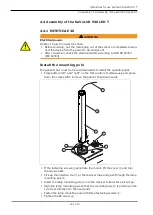
Plug the control and supply cables
①
into the line adapter
②
.
▶
Plug the control cable
④
(X87) into slot
⑤
(X87) on the central control PCB.
▶
Plug the supply cable
③
(X8) into slot
⑥
(X8) on the central control PCB.
Setting the CAN terminating resistance
Note
The CAN terminating resistances must be set correctly to ensure faultless
functioning of the ESTETICA E70 and E80. The setting is dependent on the
configuration of the device. There are two CAN circuits, the CAN circuit device
and the CAN circuit patient chair in every treatment unit. The circuits can be
set independently of each other. After the installation of the KaVoLUX 540
LED, only the CAN circuit must still be set.
35 / 110
Summary of Contents for LUX 540 LED T
Page 1: ...Instructions for use KaVoLUX 540 LED U T...
Page 109: ......
Page 110: ...1 008 8651 Fk 20190603 12 en...

