Instructions for use KaVoLUX 540 LED U / T
4 Assembly | 4.5 Ceiling assembly of the KaVoLUX 540 LED T
64 / 110
4.5 Ceiling assembly of the KaVoLUX 540 LED T
Note
Follow the instructions of the building department and building code.
The quality of the ceiling must meet the load bearing ability for buildings in
accordance with DIN 1055 page 3.
Retention forces of 1.8 kN per fastening screw must be ensured for the
mounting of the ceiling adapter to the ceiling. This can be achieved for ex-
ample through:
- The mounting material included in the delivery (the supplied heavy-duty
anchors are permitted for cement ceilings)
- For ceilings of lesser stability (wood, hollow shell or similar) it is necessary
to use an appropriate fastening material for professional mounting (not in-
cluded in the scope of delivery)
- You can find further information concerning the mounting the ceiling ad-
apter in the installation plan
- The installing technician is responsible for the professional performance of
the installation
The ceiling assembly of the KaVoLUX 540 LED T comprises the following steps:
▪ Mount the ceiling adapter
▪ Install the swivel arm
▪ Install the stay bar
▪ Connecting the lines
▪ Affix the covers
Mount the ceiling adapter
▶
Determine the location on the ceiling for attachment according to installa-
tion plan (
Mat. no. 3.000.2059
, included in the delivery of the ceiling
mounting kit).
▶
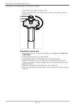
Adhere the self-adhesive drilling template
①
to the ceiling mounting site so
that the arrow is facing 6 o'clock.
Die Lage des Installationsrohrs fŸr die elektrische
Netzleitung 3x 1.5 mm2 und der PA Leitung 1x 4 mm2
soll sich in dem Bereich von dieser …ffnung befinden .
I est important que le tuyau d'installation pour l a
conduite d'alimentation lectique 3x1,5 mm2 et la
conduite quipotentielle 1x4 mm2 se trouv e
ˆ proximi t d'une de ces ouvertures.
The installation tube for the electric power lin e
3x1,5 mm2 and the potentional balance line 1x4 mm 2
should be near to one of these openings.
El tubo de instalaci—n para la linea el ctrica de la
red 3x1,5 mm2 y de la linea potencial compensatora 1x4 mm2
debe de encontrarse cerca de uno de estos orificios.
Fu§ende des Behandlungsstuhles
foot-end of the chai r
c™t repose-pieds du fauteuil
lado del pie del sillon
100mm tief gebohr
t
100mm per c en profondeu
r
100mm deep drille
d
100mm profundo tolandrad
o
1
▶
According to the drilling template, drill three 100 mm deep holes for an-
chors.
▶
Insert anchor
②
and let approx. 25 mm project.
Summary of Contents for LUX 540 LED T
Page 1: ...Instructions for use KaVoLUX 540 LED U T...
Page 109: ......
Page 110: ...1 008 8651 Fk 20190603 12 en...


