Instructions for use KaVoLUX 540 LED U / T
4 Assembly | 4.5 Ceiling assembly of the KaVoLUX 540 LED T
Note
The conductor sheath may only extend 2 mm into the protective sleeve.
▶
Draw the mains cable through cover
②
(
Mat. no. 1.004.5488
).
▶
Insert the cover into the borehole of the swivel arm and fix with screws
③
(
Mat. no. 0.261.5031
) and plate nut (
Mat. no. 1.004.5511
).
▶
Insert the litz wires
①
according to the connection diagram on the back of
the switch.
Line No.
Switch No.
1
1
1A
1A
2
2
2A
2A
▶
Carefully snap in the switch and cover into the swinging arm hole, and
screw the cover tight with the screws
③
.
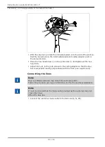
Install the stay bar
▶
Mount the intermediate plate
④
of the stay bar
⑥
with the elongated slots
⑤
and
⑧
to the grub screws
①
,
②
and
③
of the ceiling adapter. Ensure
that the slot
⑧
meets the grub screw
②
.
69 / 110
Summary of Contents for LUX 540 LED T
Page 1: ...Instructions for use KaVoLUX 540 LED U T...
Page 109: ......
Page 110: ...1 008 8651 Fk 20190603 12 en...


