background image

Maintenance

10 --- 53

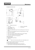
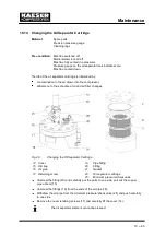
Open the air filter housing:

Pull the retaining clips (1) outwards and remove the cap (2).

Pull out the air filter cartridge (3) by turning lightly.

Clean the sealing surfaces and the air filter housing.

Do not wet ---clean the air filter element.

Clean the air filter cartridge by tapping

Renew the cartridge after two years or after it has been cleaned five times.

Tap the cartridge on the end a number of times with the palm of the hand.

Clean the sealing faces.

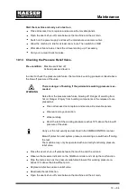
Cleaning the air filter cartridge with compressed air

Use dry compressed air at not more than 5 bar to blow dirt from the air filter cartridge
from inside to outside.

Close the air filter housing

Insert the filter cartridge.

Push on the housing and close the retaining clips.

Close all access doors and replace all cover panels.

Switch on the power supply and reset the maintenance interval counter.

10.6

Filter mat maintenance (control cabinet ventilator)

Material:

Warm water and household detergent
Spare parts (as required)

Pre --- condition: Machine switched off.

Mains isolator locked off
Machine cooled down.

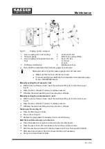
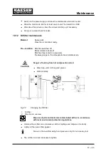
Fig. 20

Control cabinet ventilator

1

Ventilator grill

2

Filter mat

Summary of Contents for CSD 82

Page 1: ...SERVICE MANUAL Screw Compressor Model CSD No 9 5700 02E Manufacturer KAESER KOMPRESSOREN GmbH 96410 Coburg PO Box 2143 GERMANY Tel 49 0 9561 6400 Fax 49 0 9561 640130 http www kaeser com...

Page 2: ......

Page 3: ...ng oil 2 5 2 7 2 Cooling Oil Volumes 2 6 2 8 Power supply 2 6 2 8 1 Power supply 2 6 2 8 2 Power supply specifications 2 6 2 9 Water cooling option K2 2 8 2 9 1 Design data 2 8 2 9 2 Cooling Water Qua...

Page 4: ...tion Conditions 5 22 5 2 1 Place of installation and space required 5 22 5 2 2 Ventilation 5 23 5 2 3 Operating in a compressed air network 5 24 6 Installation 6 25 6 1 Safety 6 25 6 2 Report any Tran...

Page 5: ...maintenance interval counters 10 47 10 2 2 Regular maintenance work 10 48 10 2 3 Oil change intervals 10 48 10 2 4 Regular service work 10 49 10 3 Cooler Maintenance 10 50 10 3 1 Air cooling option K...

Page 6: ...Service and Repair 11 68 12 De commissioning Storage and Transport 12 75 12 1 De commissioning 12 75 12 2 Packing 12 75 12 3 Storage 12 75 12 4 Transporting 12 76 12 5 Disposal 12 76 13 Annex 13 77 1...

Page 7: ...Fig 15 Switching off in an emergency 8 33 Fig 16 Acknowledging and Resetting Warning and Alarm Messages 8 34 Fig 17 Cleaning the cooler 10 50 Fig 18 Cooler filter mats 10 51 Fig 19 Air filter maintena...

Page 8: ...T 10 K 2 8 Tab 20 Water cooling design data T 30 K 2 8 Tab 21 Cooler specification water cooling 2 8 Tab 22 Cooling Water Quality 2 9 Tab 23 Water Quality Specification 2 9 Tab 24 General specificati...

Page 9: ...from KAESER Make sure you give the data from the nameplate 1 3 Copyright This service manual is copyright protected Queries regarding use or duplication of the documentation should be referred to KAE...

Page 10: ...Regarding this Document 1 2 1 4 2 Miscellaneous notices and symbols Here is a task to be carried out This symbol identifies environmental protection measures This indicates important information...

Page 11: ...ooling air filter mat K3 Additional fan for fitted exhaust ducting K4 Machine mountings H1 Prepared for heat recovery W1 Internal heat recovery T 25K W2 Internal heat recovery T 55K W3 Modulating cont...

Page 12: ...of the pressure relief valve bar CSD 82 CSD 102 CSD 122 8 11 5 11 5 11 5 11 14 14 14 15 16 16 16 Tab 6 Pressure relief valve setting 2 5 Sound Pressure Level Operational state under load at rated spee...

Page 13: ...motor data option K2 2 7 Cooling oil Ordering see Spare Parts Operating Materials Service chapter 11 2 7 1 Recommended cooling oil The standard factory filling is SIGMA FLUID PLUS SIGMA FLUID FGL FGH...

Page 14: ...umes 2 8 Power supply See electrical diagrams in chapter 13 2 4 2 8 1 Power supply The machine is designed for an electrical supply in accordance with EN60204 1 IEC 204 1 section 4 3 In the absence of...

Page 15: ...CSD 122 Pre fuse A 200 224 Supply mm2 4 x 95 4 x 120 Consumption A 160 191 Tab 15 Supply 230V 3 60Hz Rated power supply 380V 10 3 ph 60Hz CSD 82 CSD 102 CSD 122 Pre fuse A 125 125 160 Supply mm2 4 x...

Page 16: ...data T 30 K Cooler specification Material of manufacture 1 4401 Solder Copper Maximum working pressure cooling water end bar 10 UNsuitable cooling medium Seawater Consult Kaeser before using cooling w...

Page 17: ...pecifica tion given below The manufacturer should be consulted before another type of heat transfer medium is used Water Quality Specification pH value 7 5 to 9 Hardness dH 4 0 8 5 Chloride Cl mg l 15...

Page 18: ...C equivalent to T 25 K option W2 CSD 82 CSD 102 CSD 122 Flow rate m3 h 1 39 1 70 2 00 Max heat capacity available kW 40 3 49 4 58 1 Max heat capacity available MJ h 145 178 209 Max heat capacity avai...

Page 19: ...eration of the installation conditions 3 2 Incorrect Use Untreated compressed air may not be used as breathing air for any process in which the air can come into contact with foodstuff 3 3 User s Resp...

Page 20: ...supervisory board Tab 27 Inspection schedule for Germany 3 4 Safety Devices Do not change bypass or disable safety devices Do not remove or obliterate labels and notices Ensure that labels and notice...

Page 21: ...n cause injury or death Serious injury or death can result from loosening or opening components under pressure Close shut off valves or otherwise isolate the machine from the air main to ensure that n...

Page 22: ...remote start command Before opening the machine switch off at the main switch and lock off to secure against unwanted or accidental switching on 3 7 Emergencies 3 7 1 Fire fighting Suitable extinguish...

Page 23: ...ection cooling air flow control Safe and reliable operation can only be ensured with the cabinet closed Latches are released by a key supplied with the machine Access doors are hinged to swing open re...

Page 24: ...s a low airend discharge temperature Cooling oil is recovered from the compressed air in the oil separator tank 7 gives up its heat in the oil cooler 9 The oil then flows through the filter 4 and back...

Page 25: ...mat 4 2 3 Water cooling option K2 Plate heat exchangers in stainless steel are used for water cooled machines Fig 4 Water cooling 1 Oil cooler 11 3 Cooling water connection 2 Compressed air aftercool...

Page 26: ...The drive motor is stopped PARTIAL LOAD option C1 The proportional controller continuously varies the degree of opening of the inlet valve and thereby the delivery rate of the compressor in re sponse...

Page 27: ...g time and the idle standstill time The shorter these time settings the sooner and more frequently the motor is stopped 4 3 4 Modulating control option C1 The modulating control mode is an extension o...

Page 28: ...ching remote control on and off The LED illuminates when the machine is under re mote control 5 Operating mode LOAD IDLE Toggles the machine between LOAD and IDLE 6 Arrow key Scrolls down menu Reduces...

Page 29: ...Alarm Blinks red when an alarm occurs Lights continuously when acknowledged 14 Communication Lights red if communication via the Profibus is inter rupted 15 Service warning LED Blinks yellow for main...

Page 30: ...ance the requirements of 94 9 EU ATEX directive for correct use in explosion hazardous areas Clean inlet air with no damaging contaminants Inlet air free of explosive or chemically unstable gas or vap...

Page 31: ...reated in the compressor room Ensure that the volume of air flowing into the compressor room is at least equivalent to that being removed from it by the compressor and exhaust fan Make sure that the m...

Page 32: ...be connected to both exhaust apertures an auxiliary fan option K4 must be installed If the machine is ordered with option K4 the auxiliary fan is already in stalled If necessary the auxiliary fan must...

Page 33: ...njury or death because of spring forces when spring loaded components are incorrectly opened dis mantled Minimum pressure check valves pressure relief valves and inlet valves are heavily spring loaded...

Page 34: ...able for the motor starting characteristics Before initial start up The control transformer in the control cabinet has connections for various supply volt ages Check that the correct connections are m...

Page 35: ...ler technical specification Connect the cooling water line to the fitting Open the shut off valve on the cooling water outlet A Slowly open the cooling water inlet shut off valve B to gradually fill t...

Page 36: ...ve pressure Blowoff pressure and capacity are related to the user s installation design Keep to the heat exchanger technical specification Connect the water lines to the fittings Open the shut off val...

Page 37: ...specified on the nameplate 2 4 Supply cable section and fuse rating adequate 2 8 2 5 All electrical connections checked for tightness 6 Shut off valve fitted to compressed air outlet 6 3 7 Connection...

Page 38: ...To prevent the overload protection switch from being triggered by voltage fluctuations tem perature influences or component tolerances the setting can be higher than the motor rated current see motor...

Page 39: ...f test and the green LED Power ON 16 lights Press the Operating state LOAD IDLE key Press the ON key 2 The green LED Machine ON lights 1 Allow the machine to idle for at least one minute This ensures...

Page 40: ...compressed air at a person or animal Ensure that no one is working on the machine all panels are in place all access doors are closed no parts of the machine are colder than 3 C Switch on at the main...

Page 41: ...ERGENCY STOP button 9 The EMERGENCY STOP remains latched in The machine pressure system is vented and the machine is prevented from re starting Starting again Pre condition Fault rectified Turn the EM...

Page 42: ...clock has control of the machine Apply the time controlled warning label to the machine where it is plainly visible BEWARE This machine is clock controlled and can start at any time 8 5 Acknowledging...

Page 43: ...The alarm LED red goes out 11 The machine is now ready to start again 8 5 2 Resetting warning messages Pre condition The cause of the warning eliminated Maintenance task completed Press the Acknowledg...

Page 44: ...ce technician only access doors Door opened during machine operation Close the door s ADT Maximum airend di scharge tempera ture exceeded Ensure adequate ventilation Ensure permitted room temperature...

Page 45: ...lf Short circuit to earth Check line and con nection Check the sensor AI 8 open cct AI 1 short cct The connection be tween the sensor and the analog input is shorted Check line and con nection Replace...

Page 46: ...pite an OFF command Check auxiliary con tact block Check 230 V avai lable for the contac tor mains cont on The mains contactor does not pull in de spite an ON com mand Check auxiliary con tact block o...

Page 47: ...and con nection Check the consu mer oil p No changeover to load as long as the minimum oil pres sure is not reached Check oil circulation Check pressure switch line and con nection Replace defective s...

Page 48: ...utlet excee ded Check the cutout line Check the cutout on the oil separator tank outlet SIGMA CONTROL T SIGMA controller housing temperature exceeded 70 C Ensure adequate ventilation Ensure permitted...

Page 49: ...ff prot Warning The blowoff pres sure of the pressure relief valve will soon be reached Change the oil sepa rator cartridge Open the shut off valve in the venting line Check the minimum pressure check...

Page 50: ...he modem Check the link be tween the SIGMA controller and the modem motor T Drive motor over heating Ensure adequate ventilation Install an extractor Clean the motor motor bearings h The service inter...

Page 51: ...gauge switch line and connection Replace defective switch Install auxiliary hea ting PD temperature Warning Compressor outlet temperature is low Check sensor regu lator Check the frequency converter P...

Page 52: ...upply to the fre quency converter Check power supply V belt tension V belt tension too low Re tension the V belts V belt tens h The service interval to the next V belt re tensioning has expired Re ten...

Page 53: ...ct level is reac hed Inlet valve defective Check the valve Compressor switc hes between load and idle more than Air receiver too small Install an air receiver of sufficient capacity hes between load a...

Page 54: ...release of spring force if spring loaded components are incorrectly opened dis mantled Minimum pressure check valves pressure relief valves and inlet valves are under powerful spring loading Do not op...

Page 55: ...ped sensors and or maintenance interval counters monitor the operational state of important functional devices Necessary mainten ance tasks are signalled by the SIGMA controller Keep a log of all serv...

Page 56: ...IGMA CONTROL but at least every 3 years Change the oil separator cartridge 10 14 Every 2000 h but at least annually Grease the motor bearings 10 7 Every 3000 h Check the coupling 10 8 Variable see bel...

Page 57: ...utilised service work must be carried out more frequently shorter intervals Interval Maintenance tasks Up to 12000 h Check valves Up to 12000 h at the latest every 3 years Change the fan motor bearin...

Page 58: ...machine damage Avoid dust disturbance Wear breathing apparatus if necessary Do not use sharp objects to clean the cooler The cooler could be damaged A severely contaminated cooler should be cleaned by...

Page 59: ...ion K2 Pre condition Machine switched off Mains isolator locked off Machine cooled down Check the cooler regularly for leaks and contamination Frequency of checking is depend ant on the characteristic...

Page 60: ...rised KAESER service agent clean the heat exchanger as soon as a pressure drop in the heat transfer medium is detected Leakage If a leak occurs cooling oil can flow into the heat transfer medium as pr...

Page 61: ...Cleaning the air filter cartridge with compressed air Use dry compressed air at not more than 5 bar to blow dirt from the air filter cartridge from inside to outside Close the air filter housing Inse...

Page 62: ...s danger of burning Wear long arm clothing and gloves Work carefully Compressor motor The motor bearings are fitted with grease nipples High temperature grease ESSO UNIREX N3 should be used for re gre...

Page 63: ...face cracks colour change Fig 22 Checking the Coupling 1 Safety screen 2 Coupling Check for uneven or noisy running Switch the machine on Check the coupling 2 for noisy or uneven running Check for dam...

Page 64: ...the user s shut off valve and the minimum pressure check valve Escaping oil mist is damaging to health Do not direct the maintenance hose at a person while venting Do not inhale oil mist or vapour Av...

Page 65: ...e closed insert the male hose fitting 6 into the hose coupl ing 3 Open the shut off valve 7 slowly to release pressure Withdraw the male hose fitting and close the shut off valve Manually venting the...

Page 66: ...lator locked off Machine cooled down Danger of explosion from oils and lubricants Danger of explosion from oil mist and vapours Fire naked flame and smoking are forbidden Damage to the machine from un...

Page 67: ...pl ing 3 Open the shut off valve 7 slowly to release pressure Withdraw the male hose fitting and close the shut off valve Manually venting the compressed air cooler With the shut off valve closed inse...

Page 68: ...closed B open 3 Hose coupling oil separator tank ven ting 8 Maintenance hose 4 Oil filling port with plug 9 Hose coupling oil drain 5 Oil level indicator 10 Shut off valve venting line 11 Shut off va...

Page 69: ...lve closed insert the male hose fitting 6 into the hose coupl ing 3 Connect the maintenance hose to an external air supply Open the shut off valve 7 until the pressure gauge on the oil separator tank...

Page 70: ...e Open the shut off valve 3 Open the shut off valve 7 slowly and allow oil and air to drain completely Check that the oil separator tank pressure gauge reads zero Close the shut off valve 2 and unplug...

Page 71: ...chine fully vented no pressure Pressure gauge on the oil separator tank indicates zero Danger of burning from hot components and oil Wear long arm clothing and gloves Work carefully Fig 28 Changing th...

Page 72: ...e blowing off Danger of scalding from hot oil Danger of injury from bursting components or the release of com pressed air Close all access doors replace and secure all removable panels Wear ear and ey...

Page 73: ...nce to the schedule of oil and air filter changes Fig 29 Changing the Oil Separator Cartridge 14 Cover 19 Pipe fitting 15 Dirt trap 20 Fitting 16 Air pipe 21 Gasket 17 Retaining screw 23 Oil separator...

Page 74: ...cartridge with gaskets and re fix the cover Renew the dirt trap 15 strainer and O ring Connect the air pipe to the minimum pressure check valve Replace and tighten all fittings Start the machine and...

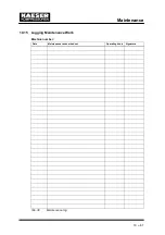
Page 75: ...Maintenance 10 67 10 15 Logging Maintenance Work Machine number Date Maintenance task carried out Operating hours Signature Tab 38 Maintenance log...

Page 76: ...original These are correct for use in our machines Compressor Name Quantity material number Air filter cartridge 1 1250 Filter mat control cabinet fan 2 1100 Filter mat cooler 1 1050 Oil filter 1 1200...

Page 77: ......

Page 78: ......

Page 79: ......

Page 80: ......

Page 81: ......

Page 82: ......

Page 83: ...least 30 minutes Machine switched off and fully vented Main supply isolator switched off and locked Allow the machine to cool down completely In water cooled machines disconnect the water supply and d...

Page 84: ...hine is over the forks Fig 30 Transport by fork truck Lifting cradle Pre condition No pressure on the sides of the machine cabinet Fig 31 Transport by lifting cradle 12 5 Disposal Pre condition Machin...

Page 85: ...ormity Machines with CE mark conform to European directives and may be operated in the EU A Declaration of Conformity is provided with the machine 13 2 Diagrams and Drawings 13 2 1 Pipeline and instru...

Page 86: ......

Page 87: ......

Page 88: ......

Page 89: ......

Page 90: ......

Page 91: ...Appendix 13 83 13 2 2 Pipeline and instrument flow diagram option C1...

Page 92: ......

Page 93: ......

Page 94: ......

Page 95: ......

Page 96: ......

Page 97: ...Appendix 13 89 13 2 3 Dimensional drawing 13 2 3 1 Air cooling option K1...

Page 98: ......

Page 99: ......

Page 100: ...Appendix 13 92 13 2 3 2 Water cooling option K2...

Page 101: ......

Page 102: ......

Page 103: ...Appendix 13 95 13 2 4 Electrical diagram...

Page 104: ......

Page 105: ......

Page 106: ......

Page 107: ......

Page 108: ......

Page 109: ......

Page 110: ......

Page 111: ......

Page 112: ......

Page 113: ......

Page 114: ......

Page 115: ......

Page 116: ......

Page 117: ......

Page 118: ......

Page 119: ......

Page 120: ......

Page 121: ......

Page 122: ......

Page 123: ......

Page 124: ......

Page 125: ......

Page 126: ......

Reviews: