


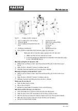

Maintenance
10 --- 48
10.2.2
Regular maintenance work
When operating conditions are unfavourable (e.g. dusty atmosphere) or
when the equipment is heavily utilised, maintenance tasks must be carried
out more frequently (shorter intervals).
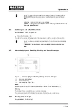
Heed controller maintenance messages.
Have KAESER service adjust the maintenance interval counters to
suit operating conditions.
Interval
Maintenance tasks
see chapter
Weekly
Check cooling oil level.
10.10.1
Weekly
Clean or renew the filter mats.
10.3.2 / 10.6
Every 1000 h
Oil and air cooler maintenance.
10.3
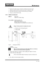
Every 1000 h
Heat recovery system maintenance.
10.4
Indicated by
SIGMA CONTROL
Air filter maintenance.
10.5
Indicated by
SIGMA CONTROL
but at least an-
nually.
Change the oil filter.
10.12
Indicated by
SIGMA CONTROL
but at least every
3 years.
Change the oil separator cartridge.
10.14
Every 2000 h, but at
least annually.
Grease the motor bearings.
10.7
Every 3000 h
Check the coupling.
10.8
Variable (see
below)
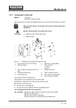
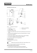
Change the cooling oil.
10.11
Annually
Check that all electrical connections are tight.
Annually
Check the pressure relief valve.
10.13
Check the oil and air coolers for leaks.
10.3
h = operating hours
Tab. 35
Regular maintenance work
10.2.3
Oil change intervals
The duty cycle and ambient conditions are important criteria for the number and length of
the change intervals.
Coolant
Maximum permissible oil change interval
[operating hours / year]
Favourable operating condi-
tions*
Unfavourable operating condi-
tions
SIGMA FLUID PLUS
SIGMA FLUID MOL
SIGMA FLUID FGL
SIGMA FLUID FGH
9 000 / 3
3 000 / 1
3 000 / 1
3 000 / 1
6 000 / 1
2 000 / 1
2 000 / 1
2 000 / 1
* Cool to moderate ambient temperatures, low humidity, high duty cycle
Tab. 36
Oil change intervals
Summary of Contents for CSD 82
Page 2: ......
Page 77: ......
Page 78: ......
Page 79: ......
Page 80: ......
Page 81: ......
Page 82: ......
Page 86: ......
Page 87: ......
Page 88: ......
Page 89: ......
Page 90: ......
Page 91: ...Appendix 13 83 13 2 2 Pipeline and instrument flow diagram option C1...
Page 92: ......
Page 93: ......
Page 94: ......
Page 95: ......
Page 96: ......
Page 97: ...Appendix 13 89 13 2 3 Dimensional drawing 13 2 3 1 Air cooling option K1...
Page 98: ......
Page 99: ......
Page 100: ...Appendix 13 92 13 2 3 2 Water cooling option K2...
Page 101: ......
Page 102: ......
Page 103: ...Appendix 13 95 13 2 4 Electrical diagram...
Page 104: ......
Page 105: ......
Page 106: ......
Page 107: ......
Page 108: ......
Page 109: ......
Page 110: ......
Page 111: ......
Page 112: ......
Page 113: ......
Page 114: ......
Page 115: ......
Page 116: ......
Page 117: ......
Page 118: ......
Page 119: ......
Page 120: ......
Page 121: ......
Page 122: ......
Page 123: ......
Page 124: ......
Page 125: ......
Page 126: ......


