


Initial Start--- up
7 --- 31
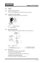
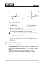
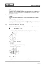
Remove the cover (3).
Note the rotational direction arrow (4).
Grasp the coupling (2) and turn it and the airend shaft (1).
Replace the coupling cover (3).
7.6
Checking Direction of Rotation
The machine is designed for a clockwise field.
Check the supply with a phase sequence indicator.
If the compressor motor turns in the wrong direction, change the motor supply phases
L1 and L2.
Alternatively, the direction of rotation can be checked by briefly switching
the machine on and off again.
Switch the machine off as soon as the direction of rotation is seen
and compare it with the direction arrows on the motor and airend.
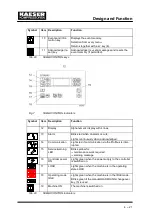
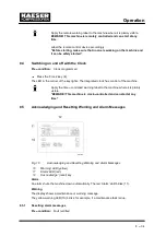
7.7
Initial Start ---up
Open the shut ---off valve to the air network.
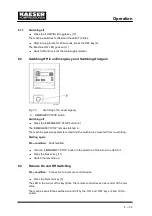
Switch on at the main supply isolator.
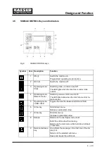
The controller makes a self---test and the green LED ’Power ON’ (16) lights.
Press the ’Operating state LOAD/IDLE’ key.
Press the ’ON’ key (2).
The green LED ’Machine ON’ lights (1).
Allow the machine to idle for at least one minute.
This ensures good distribution of cooling oil.
Press the ’Operating state LOAD/IDLE’ key.
The machine switches to the LOAD state and delivers compressed air.
Watch for any faults occurring in the first hour of operation.
After the first 50 operating hours carry out the following:
Check that all electrical connections are tight.
7.8
Setting Network Pressure
The network pressure (working pressure) is set at the works.
Adjustment is possible to suit individual operating conditions.
Network pressure setting is described in the SIGMA CONTROL service manual.
The machine may toggle a maximum of twice per minute between LOAD
and IDLE.
Reducing starting frequency:
Increase the difference between cut ---in and cut ---out pressure.
Add an air receiver downstream to increase buffer capacity.
Summary of Contents for CSD 82
Page 2: ......
Page 77: ......
Page 78: ......
Page 79: ......
Page 80: ......
Page 81: ......
Page 82: ......
Page 86: ......
Page 87: ......
Page 88: ......
Page 89: ......
Page 90: ......
Page 91: ...Appendix 13 83 13 2 2 Pipeline and instrument flow diagram option C1...
Page 92: ......
Page 93: ......
Page 94: ......
Page 95: ......
Page 96: ......
Page 97: ...Appendix 13 89 13 2 3 Dimensional drawing 13 2 3 1 Air cooling option K1...
Page 98: ......
Page 99: ......
Page 100: ...Appendix 13 92 13 2 3 2 Water cooling option K2...
Page 101: ......
Page 102: ......
Page 103: ...Appendix 13 95 13 2 4 Electrical diagram...
Page 104: ......
Page 105: ......
Page 106: ......
Page 107: ......
Page 108: ......
Page 109: ......
Page 110: ......
Page 111: ......
Page 112: ......
Page 113: ......
Page 114: ......
Page 115: ......
Page 116: ......
Page 117: ......
Page 118: ......
Page 119: ......
Page 120: ......
Page 121: ......
Page 122: ......
Page 123: ......
Page 124: ......
Page 125: ......
Page 126: ......


