
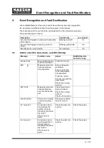


Event Recognition and Fault Rectification
9 --- 42
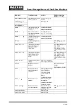
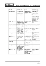
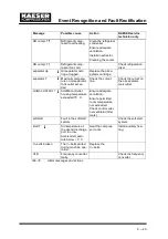
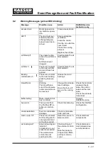
Message
KAESER service
technician only
Action
Possible cause
error: RS 485
Wrong configuration
or transmission er-
ror.
Bit rate and charac-
ter frame for both
subscribers identi-
cal.
Check the link/inter-
face connections
between the two
controllers.
Check maximum
cable length and
screening.
Check interface pa-
rameters.
1 master and 1 slave
configured.
ext. message 0
Rectify fault.
...
ext. message 5
flash memory
Internal controller
memory error.
Exchange the cont-
roller.
mains voltage
1. power failure:
Machine was re---
started automati-
cally.
Check power supply
voltage.
Check door inter-
lock.
modem problem
SIGMA CONTROL
does not recognise
the modem.
Check the link be-
tween the
SIGMA controller
and the modem.
motor T
Drive motor over-
heating.
Ensure adequate
ventilation.
Install an extractor.
Clean the motor.
motor bearings h
The service interval
to the next motor
bearing change has
expired.
Change motor bear-
ings.
motorstarts /h
The permissible
number of motor
starts was exceeded
in the last 60 minu-
tes.
Extend the idle pe-
riod.
Increase capacity of
air receiver.
Increase cross---sec-
tion of piping be-
tween compressor
and air receiver.
Check pressure
transducer.
Replace defective
sensor.
motor starts /d
The permissible
number of motor
starts was exceeded
in the last 24 hours.
Extend the idle pe-
riod.
Increase capacity of
air receiver.
Increase cross---sec-
tion of piping be-
tween compressor
and air receiver.
Check pressure
transducer.
Replace defective
sensor.
neutral p ---switch
Rectify fault
neutral T---switch
Rectify fault
Summary of Contents for CSD 82
Page 2: ......
Page 77: ......
Page 78: ......
Page 79: ......
Page 80: ......
Page 81: ......
Page 82: ......
Page 86: ......
Page 87: ......
Page 88: ......
Page 89: ......
Page 90: ......
Page 91: ...Appendix 13 83 13 2 2 Pipeline and instrument flow diagram option C1...
Page 92: ......
Page 93: ......
Page 94: ......
Page 95: ......
Page 96: ......
Page 97: ...Appendix 13 89 13 2 3 Dimensional drawing 13 2 3 1 Air cooling option K1...
Page 98: ......
Page 99: ......
Page 100: ...Appendix 13 92 13 2 3 2 Water cooling option K2...
Page 101: ......
Page 102: ......
Page 103: ...Appendix 13 95 13 2 4 Electrical diagram...
Page 104: ......
Page 105: ......
Page 106: ......
Page 107: ......
Page 108: ......
Page 109: ......
Page 110: ......
Page 111: ......
Page 112: ......
Page 113: ......
Page 114: ......
Page 115: ......
Page 116: ......
Page 117: ......
Page 118: ......
Page 119: ......
Page 120: ......
Page 121: ......
Page 122: ......
Page 123: ......
Page 124: ......
Page 125: ......
Page 126: ......


