background image

19

Installation and Preparation

1. Press the [MENU] button.

• Opens the menus in accordance with the instructions 

provided in MENU Screen Operations (page 17) in the 

sequence of [MENU] 

 [OPERATION MENU] 


[CLOCK SET].

* The time cannot be set when the VR-509 is recording, 

during DVD exporting, or when operating in the timer 

mode.

* Additionally, the time cannot be set when synchronization 

with the web browser NTP server has been activated. 

(See page 78)

* Take care when changing the date and time settings if 

recording data is stored on the hard disk. If the dates and 

times are duplicated or set earlier, there is a chance that 

the playback, skip, jump, search and other operations will 

not be performed normally.

2. Select your desired item with [

W

/

X

], and then press 

[–/+] to change the value settings.

• Set the current date and time in “D”, “M”, “Y”, “H” and 

“M”.

3. Press the [SET] button.

• The confirmation screen will be displayed.

4. Select [SAVE] and press the [SET] button.

• The date and time will now be set. The clock will start 

operating at the set time with the second value at 00.

„

The “seconds” display is adjusted by pressing [PLAY 

STOP] while pressing down on [FUNCTION]. However, this 

will not be reset during recording.

• When the “seconds” value is 29 or less, the “minutes” 

value remains unchanged, and the “seconds” value is 

reset to 00.

• When the “seconds” value is 30 or more, the “minutes” 

value is increased by one, and the “seconds” value is 

reset to 00.

„

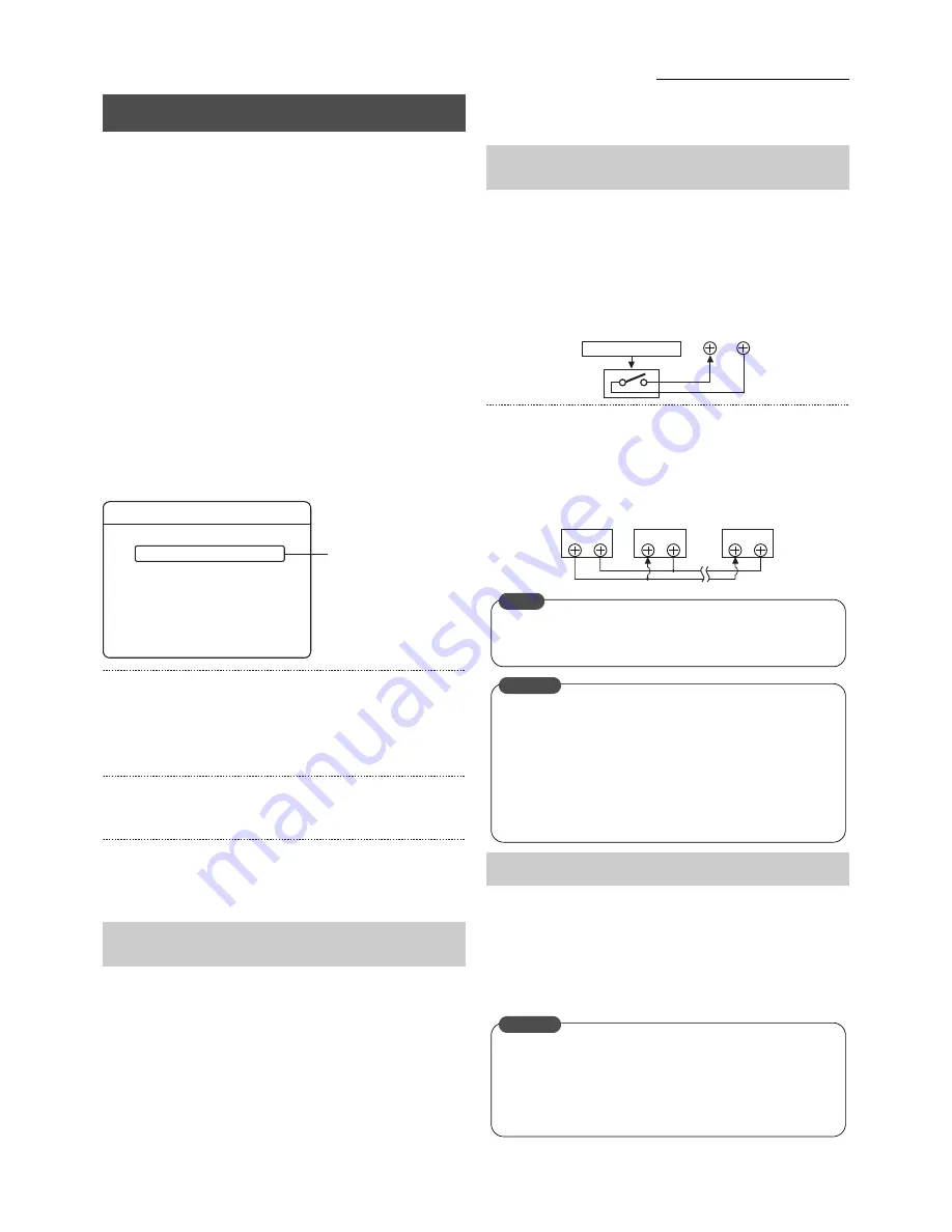
Clock Reset signal input terminal

The recorder’s clock will be reset when the relevant signal 
is input. The method of resetting the clock is the same as 
explained above in “Adjusting the seconds display with 
button operations.”
• It is possible to align the time with the master clock and 

the clocks on other equipment by receiving signals.

„

Clock Reset signal output terminal

The clock reset signal is output in accordance with the 
following timing:
• When the recorder’s internal clock reaches 00:00 and 12:00.
• It is possible to align the clock with two or more VR-509 

units in calibrations of seconds.

It is possible to adjust the clock by connecting to the NTP 
server. See the section on “Adjusting the Clock with the NTP 
Server” on page 78 for more details.
* The internal clock is accurate to within about 60 seconds per 

month. (If used in a 25°C environment) 
For greater accuracy, access the NTP server.

* See “Using the NTP Server Function” on page 107.

* It is recommended that the clock is adjusted to the correct 

time once per month to obtain accurate times.

Setting the Date/Time

Adjusting the “seconds” Display with Button 
Operations

CLOCK SET

0 1 / 0 1 / 2 0 0 6              0 0 : 0 1

 D /  M   /    Y                      H : M

2.

Adjusting the “seconds” Display with the Signal 
Input/Output Terminal

Adjusting the Clock with the NTP Server

CLOCK

RESET IN COM

External master clock

CLOCK

RESET OUT COM

CLOCK

RESET IN

COM

CLOCK

RESET IN

COM

1st VR-509

2nd VR-509

LAST VR-509

When the [CLOCK RESET OUT/IN] terminal is connected, 
the time for two or more VR-509 units will be synchronized 
twice a day at 12:00 noon and midnight.

MEMO

Make sure the power supply to the relevant units has 
been switched off before establishing the connection.

When the clock reset output terminal is to be 
connected in an array with multiple units, make sure all 
units are of the same type. Malfunctions will occur if the 
voltages on the input devices are not aligned. Also, 
note that there are cases where the clock will be reset 
for all other input units if the power supply to one of 
them is switched off.

CAUTION

When aligning the clock during recording with the clock 
reset input or with the NTP server, there is a chance that the 
recording time will be duplicated if the clock has advanced 
past the actual time.
The search and audio playback functions will not operate 
normally in this event.

CAUTION

Summary of Contents for VR-509E

Page 1: ...E before operating this unit For the setting method refer to Setting up Areas on page 18 LLT0094 001C Precautions for use z The hard disk drive HDD contained within this Digital video recorder is a fragile precision apparatus Handle it with extreme care and do not subject it to physical shock z The HDD is most susceptible to damage when the unit is on or when the HDD is being accessed z Before mov...

Page 2: ...ed electrician 3 Extension cord if used must be three core correctly wired Caution for AC Power Cord FOR YOUR SAFETY PLEASE READ THE FOLLOWING TEXT CAREFULLY Appropriate AC Power Cord must be used in each local area POWER SYSTEM Connection to the mains supply This unit operates on voltage of 220 V to 240 V AC 50 Hz 60 Hz WARNING TO REDUCE THE RISK OF FIRE OR ELECTRIC SHOCK DO NOT EXPOSE THIS APPLI...

Page 3: ...for proper treatment recovery and recycling in accordance with your national legislation By disposing of this product correctly you will help to conserve natural resources and will help prevent potential negative effects on the environment and human health which could otherwise be caused by inappropriate waste handling of this product For more information about collection point and recycling of th...

Page 4: ...NEL WEB 27 Types of Recording 28 Making Normal Recordings 29 Making Normal Recording with the EXT REC I O Terminals 29 Recording Status Notification 29 Setting up the RECORD SETUP 30 Setting the REC PATTERN SET 31 Operation Setup RECOVERY REC REC INDICATOR REPEAT REC 32 ALARM Recording 33 Setting the ALARM TERMINAL 33 Setting the ALARM Recording 34 Ending the ALARM Recording 34 Using the Motion De...

Page 5: ...able 65 Setting up a Network for VR 509 66 Setting up a PC Network 67 Connecting Login to the Network 68 Live Image Display 69 Adding to the Weekly Timer 70 Changing and Deleting the Weekly Timer 70 Adding to the Date Timer 71 Deleting the Date Timer 71 TIMER MODE 72 ALARM SEARCH 73 TIME DATE SEARCH 74 Playback Image Display 75 Inputting a Camera Title 76 Covert Channel Setting for Live image Play...

Page 6: ...ng 105 Skip jump 106 Using the NTP Server Function 107 Activating ActiveX Control and Plug ins 108 Notes Related to Summer Time 109 Recording Duration 110 DVD Recording Duration 112 Time Required for DVD Exporting 113 Installing Additional External Hard Disk Drives 114 Changing to External Hard Disk Drives 114 Disconnecting External Hard Disk Drives 115 1 Electrical Specifications 116 2 List of RS...

Page 7: ... illegal recording operations 1 Sets the Operation Lock See page 48 Sets up the operation lock parameters and the cancellation method Operations cannot be locked or cancelled when the setup menus are displayed or during playback All button operations will be locked when PASSCODE MODE 2 is selected as the operation lock release method The button operations selected with OPERATION LOCK will be locke...

Page 8: ...damage Wrap the recorder in protecting packing to prevent physical shocks Handling Handle this equipment with care Do not subject it to physical shock Do not unplug the power cord during recording or playback or when the HDD is being accessed The hard disk is a consumable item Replacement is recommended after 10000 hours of use if use in a 25 C environment For information on maintenance planning a...

Page 9: ...ictly prohibited If the feet on the base of the unit are to be removed make sure that screws with a length of 8mm or less are used when reattaching them The width of the borders on split screens dark portion may vary according to the type of input signal This is a characteristic of the camera input signal and is not a defect Contact your nearest JVC dealer if you wish to improve the condition of t...

Page 10: ...ommunication control terminals on flash memories sold separately additional hard disk drives sold separately Page 114 and UPS sold separately Keypad and Camera Input indicator 1 to 9 Selects the camera input when viewing live images and when playing back recorded images The indicator that corresponds to the selected camera input is illuminated And also these buttons are used as numeric keys S T W ...

Page 11: ... Buttons REC STOP Button Starts and ends recording Press for at least two consecutive seconds to stop recording Page 29 PLAY STOP Button Stops playback and still image playback When recording and playing back simultaneously playback is stopped and recording is activated PLAY PAUSE Buttons and indicators Displays the playback menu EVENT SEARCH screen during live image display and recording Pauses w...

Page 12: ...ont panel VGA OUT VGA Output Terminal D SUB 15 PIN Outputs live images playback images and the menu screens Outputs the same contents as VIDEO OUT Page 24 LAN Connection Interface 100 Base T For connection to the Intranet and other networks using a LAN cable Page 65 RS 232C Remote Terminal D sub 9 PIN Enables the VR 509 to be controlled from an external source when connected to a personal computer...

Page 13: ...WARNING OUT Terminal Outputs a signal when an operation abnormality or error occurs on the hard disk or other Page 96 EXT REC IN Terminal Activates recording with an external signal Page 29 OPE ON OFF Terminal Switches between OPERATE ON or OFF when the signal is input Page 16 SPOT 1 2 Terminal The input signal selects the image to be output with SPOT OUTPUT Page 26 COMMON Terminal The common grou...

Page 14: ... Reset Input Set the output impedance to 10kΩ or less Make Contact Input REC OUT Record Status Output Open collector DC15V 10mA or less WARNING OUT Warning Output Open collector DC15V 10mA or less OPE ON OFF Operate ON OFF Switches to OFF when OPERATE is set at ON Switches to ON when OPERATE is set at OFF Make Contact Input SPOT 1 2 Spot Output Selection The SPOT output more is selected in accorda...

Page 15: ... occurs with image signal input The number of the camera is displayed in If recording is continued in this state there is a possibility that accurate recording will not be possible not only with the affected camera but also with normally operating cameras In this case either invalidate the input recording for which the problem occurred or resolve the cause of the problem immediately See CAMERA SET...

Page 16: ... OPERATE indicator will be extinguished Activate the OPERATE OFF mode before switching off the power Switch off the power supply to the VR 509 before switching off the external hard disk drive Set the OPERATE ON OFF terminal to Low 0V when in the OPERATE OFF mode A system check will be started The OPERATE ON mode will then be activated Operations are possible when the on screen display REC STOP ma...

Page 17: ...ngs will not be saved in this event There are fields that cannot be updated or saved during recording There are fields that cannot be changed when in the timer mode Press the FUNCTION button to display the user guidance in the menu screen display mode Press the RETURN button or the MENU button for at least one consecutive seconds to close the menu screen MENU Screen Operations Displaying the MENU ...

Page 18: ...isplayed DD Day MM Month YY Year Selects the area closest to your own address Selects the language used for on screen displays The menus user guidance and warnings can be displayed in either English German French Italian or Spanish The default setting is English ENGLISH GERMAN FRENCH ITALIAN SPANISH User Guidance See Displaying User Guidance on the Menu Screen on page 17 3 Press the SET button The...

Page 19: ...t terminal The clock reset signal is output in accordance with the following timing When the recorder s internal clock reaches 00 00 and 12 00 It is possible to align the clock with two or more VR 509 units in calibrations of seconds It is possible to adjust the clock by connecting to the NTP server See the section on Adjusting the Clock with the NTP Server on page 78 for more details The internal...

Page 20: ...ge period only acts as a guidelines as the actual period of storing images may differ depending on amendments to the frame rate quality and other settings in CAMERA SETUP 3 Refer to the section on Recording Duration on page 110 for further details on the storage period for recorded images ON OFF Set whether to record sound audio when in the NORMAL REC and ALARM REC modes Set the action when the re...

Page 21: ... The update confirmation screen will be displayed when FINISH is selected Select SAVE and then press SET to confirm the setting and complete the CAMERA SETUP procedure When the settings are updated after being amended all of the current REC PATTERN settings will be amended to reflect the amendments back onto the STANDARD and REC PATTERN 1 to 9 settings Installation Settings continued CAMERA SETUP ...

Page 22: ...AD C screen 4 Press 4 to display the 6 WAY screen 5 Press 5 to display the 9 WAY screen The screen layout for the split screens are set on the LIVE PICTURE screen Page 23 Press the SPLIT button to display the single screen The single screen that was previously set up will be displayed Press the SEQUENCE button for at least one second to activate QUAD SEQUENCE screen Possible only when the QUAD scr...

Page 23: ...een inside the blue border The blue border moves to the next sub screen The above is an example of QUAD screen Press the 0 button to select the black screen Press the SEQUENCE button for at least one second to return the blue border to the previous sub screen and display the screen as it was prior to amendment 5 Press the SPLIT button The split screen selection screen will be displayed Repeat proc...

Page 24: ...n which VIDEO OUT images will seem different if these settings are changed 1 Press the MENU button The MENU OPERATION MENU MONITOR SEQUENCE TIME screens will be displayed in this sequence in accordance with the MENU Screen Operations explained on page 17 2 Select your desired item with the S T keys and then change the value of the setting with Settings Set the time at which each screen is to be sw...

Page 25: ...EC images ALARM DETECT AL will be displayed in red when an ALARM REC is operated DISK CAPACITY Displays the remaining disk capacity when the REPEAT REC parameter has been set at OFF displayed as The remaining disk capacity will not be displayed when the REPEAT REC parameter is set at ALL or ALARM LOCK PLAYBACK Displays the playback mode or etc and the operation status blue circle etc DB display du...

Page 26: ...nel for 400 ms or more The setup screen will change to SPOT output when the SPOT1 and SPOT2 terminals are input Displaying the next screen When in the single screen mode Switched alternately in the sequence 1 2 3 9 1 When in the QUAD screen mode Switched alternately in the sequence QUAD A QUAD B QUAD C QUAD A When in the 6 WAY and 9 WAY screen modes Input is disabled Will not function during seque...

Page 27: ...n a personal computer Page 69 Viewing Live Images Using a PC Page 73 Viewing Playback Image Using a PC 1 Press the MENU button The MENU OPERATION MENU MONITOR COVERT CHANNEL COVERT CHANNEL WEB screens will be displayed in this sequence in accordance with the MENU Screen Operations explained on page 17 2 Select your desired item with the S T keys and then change the value of the setting with Settin...

Page 28: ...tarted when signals are input or motion is detected in the pause mode and during normal recording and timer recording The following three types of alarm recording are available Emergency Recording Recording is started when a signal is input to the EMERGENCY terminal See page 33 Passcode Error Recording See page 30 Alarm Recording Signal input terminal Recording is started when a signal is input to...

Page 29: ...ss the REC STOP button for approximately two consecutive seconds to stop recording When the EXT REC IN is set at MANUAL Normal recording is executed while the EXT REC IN terminal is in MAKE state Recording is stopped when the EXT REC IN terminal is in OPEN state Press the REC STOP button for approximately two consecutive seconds to stop recording The status of the recording can be examined during ...

Page 30: ...p recording by pressing the ALARM RESET button OFF Recording not started when the wrong passcode is entered 10 SEC 20 SEC 30 SEC Starts recording only to the period of time set when the wrong passcode is entered Page 54 Pass Code Setup PROGRAM TIMER Records according to weekly program timer and daily program timer REC PATTERN 1 9 Records according to the respective REC PATTERN setting The tamperin...

Page 31: ... recordings have been started H High High quality recording N Normal Normal quality recording B Basic Basic quality recording L Lowest Lowest quality recording Sets the motion detect sensitivity OFF Disables the motion detect mode NORM Detects the motion detect sensitivity in normal mode USER Detects the motion detect sensitivity in free mode DOOR H DOOR L HALL H HALL L CHECK H CHECK L ATM H ATM L...

Page 32: ...with the same settings prior to the power failure only when recording was being carried out before the power failure occurred Recording will be carried out in accordance with the timer settings during timer operations Sets whether or not to illuminate the recording indicator during recording OFF Not illuminated ON Illuminated Sets the operations to be carried out when the hard disk runs out of spa...

Page 33: ...ea Page 37 Recording is started when motions is detected in the input image 1 Press the MENU button The MENU RECORD SETUP ALARM TERMINAL screens will be displayed in this sequence in accordance with the MENU Screen Operations explained on page 17 The screen will display a matrix that shows the alarm input terminals on the vertical axis and the camera input on the horizontal axis If a camera input ...

Page 34: ...cording are explained on page 105 Alarm recording includes motion detection will not be carried out when the setup menu is open Alarm recording is stopped when ALARM RESET button is pressed and when a signal is input to the ALARM RESET terminal during alarm recording alarm input terminal motion detection When alarm recording is cancelled alarm recording triggered by new motion detection signals wi...

Page 35: ...ction Area Count Using the Motion Detection Function Motion Detection with Pre Determined Sensitivity Scene Detailed Settings of Sensitivity DYNAMIC SENSITIVITY LEVEL STOP LEVEL TARGET AREA LEVEL NORM 8 2 2 USER 1 to 10 8 default 1 to 3 2 default 1 to 10 2 default DOOR H 9 1 1 DOOR L 8 3 2 HALL H 9 1 1 HALL L 8 3 2 CHECK H 9 1 1 CHECK L 8 3 2 ATM H 8 1 1 ATM L 7 3 3 LOBBY H 10 1 1 LOBBY L 9 3 2 GA...

Page 36: ...The larger the value the more difficult to discontinue alarm detection Setting Range 1 to 3 The level value for the size of the subject to be detected The higher the value the more difficult it is to detect small motions Setting Range 1 small to 10 large 4 Press the SET button The confirmation screen will be displayed 5 Select SAVE with the W X keys and then press SET button Use the manual setting...

Page 37: ...he Motion Detection Check screen will be displayed when SET button is pressed on the MOTION DETECT AREA SET screen Motion Detection Check screen 1 Press the keys to select the motion detection sensitivity 2 Press the SET button to check motion detection The color of the circle at the top left hand side of the check screen is set in accordance with the following conditions Red Motion detection oper...

Page 38: ...ON and OFF can be selected for this parameter When ON has been selected the timer will be executed on a constant basis Sets the day of the week to be recorded when DAY has been selected for the starting day The desired day of the week MON etc will be recorded is displayed for days on which recording is not activated 9 Press the SET button A confirmation screen will be displayed 10 Select SAVE with...

Page 39: ...e parameter or re enter the correct parameter 1 Set the TIMER MODE REC PATTERN setting on the RECORD SETUP screen to PROGRAM TIMER See page 30 2 Press the TIMER MODE button on the front panel to illuminate the TIMER MODE indicator The system will enter the timer standby mode Performs recording with the setting specified for WEEKLY TIMER or DATE TIMER The following operations are not possible when ...

Page 40: ...for Images According to Date Time Jog Shuttle Playback Page 43 Adjusting Playback Speed Skip Playback Page 44 Skipping Recorded Images Playing Back Images Pausing during Playback Ending Playback EVENT SEARCH CONTINUOUS PLAYBACK ALARM LIST SEARCH SEARCH DATE 2 0 SKIP SET Play with PLAY PAUSE button SKIP OLDEST EVENT 2 LATEST EVENT Playing Back during Recording Simultaneous Playback Mode There are c...

Page 41: ...screen 3 Press 3 to display the QUAD C screen 4 Press 5 to display the 9 WAY screen The screen layout for the split screens are set on the LIVE PICTURE screen Page 23 The position of the border will differ slightly with live images and playback images The 6 WAY cannot be activated even if the 4 button is pressed when the split screen mode is in use The 9 WAY screen will be activated in this case P...

Page 42: ...he recorded image to be played back with S T and then press the SET button The alarm image selected will be played back Press the button to jump to the oldest of 100 items of data If the number of items remaining is less than 100 the oldest list will be displayed in the center Press the button to jump to the most recent of 100 items of data If the number of items remaining is less than 100 the mos...

Page 43: ...ed below High frame rate recording 25 frame recording on a single screen display Slow playback with every second frame Other modes on single screen displays All frames played back slowly Split screen displays Slow playback with a maximum of two or three frames every second Rotate the jog shuttle during playback a single frame will be played back Rotate the dial clockwise to playback a single frame...

Page 44: ...0 MIN 30 MIN 1 HOUR 4 HOURS 1 DAY 1 WEEK The duration of each jump when TIME has been specified for the SKIP MODE 4 Press the SET button A confirmation screen will be displayed 5 Select SAVE with W X and then press the SET button 6 Press RETURN to return to the EVENT SEARCH screen 7 Select CONTINUOUS PLAYBACK to activate the playback mode 8 Press the SKIP button during playback to jump to the prev...

Page 45: ...ied input or not Or sets the input audio that was not specified for the AUDIO 1 link or AUDIO 2 link 1 Press the MENU button Opens the menus in accordance with the instructions provided in Changing MENU Settings page 17 in the sequence of MENU OPERATION MENU MONITOR AUDIO OUT 2 Select your desired item with S T and change the setting value with Settings z NOT DESIGNATED The link is not specified C...

Page 46: ...or the live display Press the 1 to 9 button while pressing down on the FUNCTION button The live images for the selected camera will be displayed The Title area will be highlighted against a blue background and the display position adjustment mode will be activated 4 Press S T W X Move the Title position to any preferred location Do not move this sub screen over the Message Display Area Warnings an...

Page 47: ...th the relevant character and press the CANCEL button 6 Press the SEQUENCE button after the camera title has been entered The confirmation screen will be displayed 7 Select SAVE and press the SET button to save the title Proceed onto entering the next camera title Press the CANCEL button to return the title to its original status Press the RETURN button to return to the previous menu A maximum of ...

Page 48: ...played 4 Select SAVE with W X and then press the SET button Menu setup is possible even when the operation lock has been activated when the CHANGE SETTING parameter on the USER settings has been set at OFF However the parameters related to the operation lock cannot be amended Amendments to the operation lock settings can only be made after the operation lock has been cancelled Table 4 Buttons to b...

Page 49: ...SET 1 Press the MENU button The MENU OPERATION MENU ONSCREEN OPERATION REAR TERMINAL screens will be displayed in this sequence in accordance with the MENU Screen Operations explained on page 17 2 Select your desired item with the S T keys and then change the value of the setting with Settings Recording will start stop with input into the EXT REC IN terminal on the rear panel OFF Signals not outpu...

Page 50: ...ctions provided in Changing MENU Settings page 17 in the sequence of MENU OPERATION MENU MAINTENANCE 2 Select MANUAL SCAN DISK with S T and then press the SET button The SCAN DISK function will be executed Hard Disk Maintenance AUTO SCAN DISK MAINTENANCE AUTO SCAN DISK MANUAL SCAN DISK ALARM LIST CLEAR DEFRAG DATABASE FORMAT MIRRORING PASSCODE SET MAINTENANCE LOG AREA SELECT OFF EXEC EXEC 3 2 MANU...

Page 51: ...on The FORMAT function will be executed When the formatting process has been completed the FORMAT SUCCEEDED screen will be displayed Operations will then automatically return to normal As the hard disk capacity displayed on the screen is calculated as 1GB 1024 3 bytes a lower capacity than actually exists will be displayed All recorded events will be erased when the formatting procedure is execute...

Page 52: ...nce of MENU OPERATION MENU MAINTENANCE MIRRORING The MIRRORING screen will be displayed 2 Check to confirm that the The mirroring is being operated message is displayed and then press the SET button The Do Mirroring Release Recovery confirmation screen will be displayed 3 Select RELEASE and press the SET button The MIRRORING SETTING will be cancelled and the MIRRORING mode will be disabled A messa...

Page 53: ...ally exists will be displayed If a defect occurs on one of the hard disks the function for exporting data onto DVDs will not operate The objective of mirroring is to protect recorded data in the event that the VR 509 hard disk malfunctions Note that there are cases where operations cannot be continued even when mirroring has been set up depending on the case of hard disk malfunction It is possible...

Page 54: ...and then amend the value of the setting with Settings OFF A warning will not be issued even when mis input occurs ONCE TWICE THRICE A warning is issued after mis input occurs consecutively for the number of times set 5 To enter or amend the sub passcode select SUBCODE with the S T keys and then press SET The sub passcode entry screen will be displayed The sub passcode cannot be set unless the pass...

Page 55: ...uted if the system fails to recognize the hard disk or malfunctions occur three times during automatic rebooting When there is a failure on the hard disk it will restart and recovery automatically The E 01 error code will be displayed on the monitor screen after the automatic rebooting procedure has been carried out Normal operations will be resumed when the automatic rebooting procedure has resto...

Page 56: ...at supports DVD R RW discs although playback performance is not guaranteed They cannot be played back on the VR 509 Consult with your nearest JVC dealer for details on suitable DVD players See Export Form on page 57 DVD video discs available on the open market cannot be played back 1 Press the OPEN CLOSE button The disc tray will open automatically 2 Place the disc on the disc tray Ensure that the...

Page 57: ...o sound will not be output even if the OPT parameter is set up Sets whether the date time stamp is to be recorded on images or not when writing is being carried out in the DVD Video format When data is being exported to a DVD RW disc all previous data on the disc will be deleted This function specifies the method of deletion COMPLETE Deletes all data This will require between thirty minutes and on...

Page 58: ...nt of time to run when the number of relevant chapters is large Incorrect entries will be highlighted with red underlines It is possible to display a message stating CAPACITY OVER on the DURATION setup screen when the capacity exceeds the volume of the DVD see the section on Error Messages below In this event select EDIT on the DURATION setup screen and press SET to amend or delete the period list...

Page 59: ...functions on the hard disk may result in the DVD export function not being able to be used When data that is less than a total of 1GB is to be exported onto a DVD R it will be expanded to approximately 1GB of data and exported accordingly depending on the rating for the DVD R This will consequently result in additional time required for the process to be completed There are cases where the CHAPTER...

Page 60: ...chapters with the SKIP button Press the HDD DVD button when displaying the live screen The display indicator will be extinguished and the HDD Operation mode will be activated It is not possible to switch across to the HDD operation mode when the DVD list or DVD MENU is being displayed or when a DVD is being played back Playing Back Exported Images on DVD DVD MENU 3 DVD INFORMATION DVD PLAY DVD EXP...

Page 61: ...pters is possible within a single title Five chapters will be displayed on each page maximum 20 pages Turn the pages with the Previous Page and Next Page keys on either side of the screen The name of the title consists of the serial number the starting time the ending time and the recording type The symbols for the recording types are shown below N Normal recordings E Emergency recordings R Alarm ...

Page 62: ...gnized will be displayed on screen To continue make sure the flash memory is connected correctly select RETRIAL on the screen and then press SET To abort the procedure select CANCEL on the screen and then press SET This message will be displayed in the following circumstances When a flash memory has not been connected When the flash memory contains a different file system A message stating Still p...

Page 63: ...CEL on the screen and then press SET This message will be displayed in the following circumstances When a flash memory has not been connected When the flash memory contains a different file system A message stating Set data save failure or Set data of the USB flash memory cannot be recognized will be displayed on screen if the procedure for downloading uploading the data fails In this case select ...

Page 64: ...n the power to the VR 509 Connecting a UPS Make sure the UPS communication cable is connected before switching on the power to the VR 509 Do not disconnect the communication cable when operations are being carried out Consult with your nearest JVC dealer for details on the UPS that can be used A USB hub is required when a UPS and an external hard disk are to be used simultaneously Make sure that t...

Page 65: ...router etc and the VR 509 to a line terminal device with a straight LAN cable Always used LAN cables that are rated Enhanced Category 5 or Category 6 z Consult the network administrator when connecting to an existing LAN line z A maximum of thirty two live images can be viewed on multiple PCs with each VR 509 unit z A maximum of one video playback image can be viewed with each VR 509 unit z It is ...

Page 66: ...DRESS 192 168 0 10 NET MASK 255 255 255 0 DEFAULT GATEWAY 192 168 0 254 Consult with the network administrator for details on the settings required to connect the recorder to a LAN network 6 Press the SET button The settings will be saved When a DHCP server has been set for METHOD the IP address allocated by the DHCP server will be displayed the next time this menu is opened cannot be amended When...

Page 67: ...et Protocol TCP IP and then click on 5 Select Use the following address 6 Set the IP Address to 192 168 0 11 7 Set the Subnet Mask to 255 255 255 0 8 Set the Default gateway to 192 168 0 254 9 Click on OK 10 Click on the button on the Local Area Connection Properties screen Ensure that the same IP address is not used within the same network environment Do not register more than one IP address for ...

Page 68: ...u 3 Displays the setup screen 4 The contents of each of the selection menu will be displayed when the cursor is placed over the top The following dialog box will be displayed when LIVE PICTURE EVENT SEARCH ALARM SEARCH and EVENT SEARCH TIME DATE SEARCH are clicked Click on INSTALL to execute the installation procedure this will not be displayed on subsequent uses Connecting Login to the Network 2 ...

Page 69: ...can be saved There are the following two methods PC SET Click on this button to save the live image display window settings onto the personal computer and to delete the live image display window settings from the personal computer The PC REGISTER DELETE screen will be displayed Click on either SAVE or DEL The saved data will be loaded when the live image display window is opened VR 509 SET Click o...

Page 70: ...d program list weekly timer settings screen will be displayed Click on CLOSE to close the window 1 Click on TIMER RECORDING WEEKLY TIMER The WEEKLY TIMER SETUP and program list weekly timer settings screen will be displayed 2 Click on the UP button A confirmation screen showing the amendments will be displayed 3 Click on the UP button on confirmation screen The program will be updated The updated ...

Page 71: ...y made The settings will be saved The updated program list date timer settings screen will be displayed Click on CLOSE to close the window 1 Click on TIMER RECORDING DATE TIMER The DATE TIMER SETUP and program list date timer settings screen will be displayed 2 Click on the DEL button A confirmation screen showing the details to be deleted will be displayed 3 Click on the DEL button on confirmatio...

Page 72: ...E in that order 2 Click the ON button The TIMER MODE will be activated 1 Click on TIMER RECORDING TIMER MODE in that order 2 Click on the OFF button The TIMER MODE will be deactivated TIMER MODE When the TIMER MODE is Deactivated When the TIMER MODE is Activated 2 2 ...

Page 73: ...t the recorded image to be played back from the list of search results 15 items will be displayed for the recording image list at one time Click on the button to open the page Next 15 Lists Displays the next screen Before 15 Lists Displays the previous screen 5 Select Recording image list Select the recording image to be played back by referring to the listed items Display Items The alarm number r...

Page 74: ...n EVENT SEARCH DATE SEARCH in that order 2 Enter the date and time of the search 3 Select the channel to be searched 4 Click on the SEARCH button Playback screen will be displayed Click on the RESET button to clear the entry TIME DATE SEARCH 2 3 4 ...

Page 75: ...ch the file is to be stored Playback Image Display 2 7 3 4 5 6 1 A message stating There is not a reply of the VR 509E will be displayed if the playback display window is opened with a window opened on the live display screen but this is not a malfunction Close the live image display window if it is open There are cases where playback will fail if it is started immediately after closing the live s...

Page 76: ...hat have been left blank when the SAVE button is pressed will be initialized Character amendments are not possible once the SAVE button has been pressed The entire title must be entered in full once again Click on the RESET button to return the settings to the VR 509 default settings 1 Click on WEB DISPLAY COVERT CHANNEL in that order 2 Change the setting See on page 27 for details 3 Click on the ...

Page 77: ...parameters when an alarm is input 5 The mail sending report settings confirmation screen will be displayed Test mail transmission is possible by clicking on TEST MAIL so check to ensure that mail can be received by the specified address Mail Notification Setting During Alarm Input MODE MAIL SMTP SERVER INTERVAL TO E MAIL FROM E MAIL SUBJECT LIST FORM LOCATION NAME 2 3 4 DOMAIN NAME DNS SERVER Ther...

Page 78: ...iled in the inquiry to a designated NTP server will be displayed Check to verify that the NTP server address was correctly entered and then repeat the registration procedure 1 Click on NETWORK NTP SERVER in that order 2 Select the No button 3 Click on the SAVE button The NTP server registration will be cancelled A confirmation screen will be displayed Adjusting Clocks with the NTP Server Registeri...

Page 79: ...played A screen stating Download data making completion will be displayed when the download has finished 3 Click on the SAVE button The FILE DOWNLOAD screen will be displayed 4 Click on the SAVE button The SAVE AS screen will be displayed 5 Click on the SAVE button The downloading procedure will be activated Downloading VR 509 Settings 2 3 4 5 ...

Page 80: ...he UPLOAD screen 5 Check the name of the file to be uploaded 6 Click on the UPDATE button The Upload re confirmation to VR 509 screen will be displayed 7 Click on the EXEC button The uploading procedure will be activated 8 Wait until the upload procedure has been completed A screen stating UPLOAD COMPLETE will be displayed when the uploading procedure has finished VR 509 will be automatically rest...

Page 81: ...ILITY OPEN SOURCE in that order Displays the information concerning OPEN SOURCE 1 Click on STATUS Displays all the setting items as a list Click on your desired item then you jumps to it Display Items WEEKLY TIMER DATE TIMER TIMER MODE COVERT CHANNEL WEB MONITOR ONSCREEN MODE SEQUENCE TIME QUAD DISPLAY COVERT CHANNEL VR 509E CAMERA TITLE RECORD SETUP REC PATTERN SET ALARM REC OPERATION AUDIO OUT A...

Page 82: ...als Character sensitive for upper case and lower case characters Enter the password once again for confirmation purposes Select from either Administrators Operators or Users Access rights for each menu 3 Click on the SAVE button Click on RESET to clear the entry 1 Click on NETWORK ACCESS USER List 2 This screen enables the access user profiles to be checked 3 Click on the UPDATE button to make any...

Page 83: ...ESET button to return to the setting values on the main unit 1 Click on DISPLAY SEQUENCE TIME in that order 2 Change the settings See page 24 for details 3 Click on the SAVE button Click on the RESET button to return to the setting values on the main unit When the display is grayed out it indicates that the camera input settings for the CAMERA SETUP 1 that correspond to the grayed out cameras have...

Page 84: ...mode to be set up 3 Change the settings See page 31 for details 4 Click on the SAVE button Click on the RESET button to return to the setting values on the main unit When the display is grayed out it indicates that the camera input settings for the CAMERA SETUP 1 that correspond to the grayed out cameras have been set to DISCONNECT See page 20 1 Click on FUNCTION ALARM REC in that order 2 Select t...

Page 85: ...nput to the right of a alarm terminal that has received an input it means it has been enabled If it remains blank it means it is disabled 3 Click on the SAVE button Click on the RESET button to return to the setting values on the main unit When the display is grayed out it indicates that the camera input settings for the CAMERA SETUP 1 that correspond to the grayed out cameras have been set to DIS...

Page 86: ...EC REPEAT REC CAMERA SETUP 2 1 WEEK OFF ALL RECORD SETUP DATE TIMER OFF ALARM REC PROGRAM TIMER WEEKLY TIMER WATER MARK TIMER MODE REC PATTERN OFF NORMAL AUDIO REC ALARM AUDIO REC OFF ALARM TERMINAL REC PATTERN SET OFF EMERGENCY REC DURATION OFF PASSCODE ERROR REC REC PATTERN SET STANDARD REC PATTERN1 REC PATTERN2 REC PATTERN3 REC PATTERN4 REC PATTERN5 REC PATTERN6 REC PATTERN7 REC PATTERN8 REC PA...

Page 87: ...N N N N N N ALARM REC F RATE ips QLY CAMERA SETUP 3 ALARM TERMINAL ALARM PORT PORT1 PORT2 PORT3 PORT4 PORT5 PORT6 PORT7 PORT8 PORT9 EMERGENCY REC 1 2 3 4 5 6 7 8 9 1 2 3 4 5 6 7 8 9 ALARM REC CAMERA INPUT DURATION PREALARM REC MOTION DETECT SET DYNAMIC SENSITIVITY LEVEL DEFAULT 8 STOP LEVEL DEFAULT 2 DEFAULT 2 TARGET AREA LEVEL MOTION DETECT AREA SET The camera is changed with a Right Left key CAM...

Page 88: ... DISP LIGHTGRAY OFF VGA OUT ENABLE SEQUENCE TIME CAMERA 1 CAMERA 2 CAMERA 3 CAMERA 4 CAMERA 5 CAMERA 6 CAMERA 7 CAMERA 8 CAMERA 9 SPLIT PICTURE 1 SEC 1 SEC 1 SEC 1 SEC 1 SEC 1 SEC 1 SEC 1 SEC 1 SEC 1 SEC QUAD QUA QUA QUA ONSCREEN MODE ON ON ON ON ON ON ON OFF DATE TIME ALARM COUNT ALARM DETECT DISK CAPACITY PLAYBACK CAMERA TITLE WARNING REC TO STOP MESSAGE AUDIO OUT AUDIO 01 LINK AUDIO 02 LINK AUD...

Page 89: ... OFF OPERATION RECOVERY REC REC INDICATOR REPEAT REC OPELOCK RELEASE OPERATION LOCK REC STOP PLAY CHANGE SETTING CHANGE MONITOR OPERATION DVD PRIOR STATE ON ALL BASIC REC STOP OFF OFF OFF OFF OFF OFF CAMERA TITLE SYMBOL ALPHAMERIC CAM1 BUZZER OFF OFF OFF OFF OFF OFF OFF OFF OFF ON ALARM HDD FULL WARNING VIDEO LOSS HDD ERROR FAN MOTOR ERROR PASSCODE ERROR POWER FAIL REC STOP BUTTON REAR TERMINAL EX...

Page 90: ...INUE MANUAL PASSCODE ERROR REC z OFF 10SEC 20SEC 30SEC TIMER MODE REC PATTERN z PROGRAM TIMER REC PATTERN 1 to 9 WATER MARK ON z OFF NORMAL REC Page 31 Items Settings F RATE ips NORMAL REC 0 08 0 2 0 4 0 8 1 7 2 5 5 z 8 3 12 5 25 ips QLY NORMAL REC H High z N Normal B Basic L Lowest F RATE ips ALARM REC 0 8 1 7 2 5 5 8 3 12 5 25 ips z AUTO QLY ALARM REC z H High N Normal B Basic L Lowest M DET z O...

Page 91: ...L 1 to 10 Factory setting 2 WEEKLY TIMER Page 38 Items Settings START DAY SUN MON TUE WED THU FRI SAT DAY START TIME 00 00 to 23 59 END DAY SUN MON TUE WED THU FRI SAT END TIME 00 00 to 23 59 MODE REC PATTERN mode STANDARD REC P 1 to 9 EXEC OFF ON WEEK REC DATE SET SUN MON TUE WED THU FRI SAT DATE TIMER Page 39 Items Settings START TIME 00 00 to 23 59 END TIME 00 00 to 23 59 MODE REC PATTERN mode ...

Page 92: ...HANNEL Page 27 Items Settings CAMERA 1 to CAMERA 9 ENABLE z DISABLE SELECT OUTPUT OFF SPOT OUT MONITOR OUT z SPOT MONITOR OUT PLAY PERMISSION ON z OFF COVERT CHANNEL WEB Page 27 Items Settings CAMERA 1 to CAMERA 9 ENABLE z DISABLE WEB PLAY PERMISSION ON z OFF CAMERA TITLE Page 47 Items Settings CAM 1 to CAM 9 20 one byte characters Factory setting CAM 01 to CAM 09 AUDIO OUT Page 45 Items Settings ...

Page 93: ...ATE COMPULSION REC REC INDICATOR Page 32 z ON OFF REPEAT REC Page 32 OFF ALARM LOCK z ALL OPE LOCK RELEASE Page 48 z BASIC PASSCODE MODE1 PASSCODE MODE2 OPERATION LOCK Page 48 OFF z REC STOP ALL USER REC STOP ON z OFF PLAY ON z OFF CHANGE SETTING ON z OFF CHANGE MONITOR ON z OFF OPERATION ON z OFF DVD ON z OFF BUZZER Page 49 Items Settings ALARM ON z OFF HDD FULL ON z OFF WARNING z OFF USER ALL VI...

Page 94: ... HOST NAME z vr509 METHOD OFF z STATIC IP DHCP IP ADDRESS z 192 168 0 10 NET MASK z 255 255 255 0 DEFAULT GATEWAY z 192 168 0 254 DNS SERVER z 0 0 0 0 MAC ADDRESS Cannot set MAINTENANCE Page 50 53 Items Settings AUTO SCAN DISK Page 50 ON z OFF MANUAL SCAN DISK Page 50 EXEC ALARM LIST CLEAR Page 53 EXEC DEFRAG DATABASE Page 51 Items Settings TIMER CONTROL ON z OFF DATE AND HOUR Date 1 to 31 specifi...

Page 95: ...LOG Page 55 EXEC DOWNLOAD SETTING Page 63 EXEC UPLOAD SETTING Page 63 EXEC AREA SELECT Page 18 Items Settings DATE DISPLAY z DD MM YY MM DD YY YY MM DD TIME ZONE z UTC London Berlin Rome Madrid Paris CET GMT 1 EET GMT 2 GMT 3 GMT 4 GMT 5 GMT 6 GMT 7 GMT 8 Japan GMT 9 GMT 10 GMT 11 GMT 12 GMT 12 GMT 11 Hawaii GMT 10 Alaska GMT 9 Pacific GMT 8 Arizona Mountain GMT 7 Central GMT 6 East Indian Eastern...

Page 96: ...y P15 P20 E 05 DETECTED 1 2 Error in the fan motor Consult your nearest JVC dealer E 06 DETECTED 1 2 EEPROM error If this error occurs due to alteration of a menu setting turn the equipment off on and check the setting If this error keeps occurring due to alteration of a menu setting or during operation consult your nearest JVC dealer E 07 DETECTED 1 2 Codec 1 error Mostly used for recording and V...

Page 97: ...ting is executed P51 P32 CAPACITY FOR EVENT IS HARDLY There is a possibility that the deletion of old events or playback is being halted prior to all of the capacity on the hard disk being used owing to the incorrect setup of the REC PATTERN parameter Amend the setting to reduce the frequency and number of times the alarm is triggered P31 NO CAPACITY FOR EVENT ANY MORE 0 The deletion of old events...

Page 98: ... The inserted disc is not supported Disc deletion failed There is a chance that an error occurred on the relevant disc P57 There is no file can be reproduced in DVD D 01 There is no file can be reproduced in DVD D 02 There is no file can be reproduced in DVD D 03 The directory for list creation does not exist The file for list creation does not exist List creation failed P60 On screen Message Caus...

Page 99: ...eck to ascertain that the settings on the ONSCREEN MODE screen are set to ON P25 Date Time is not recorded Check the DATE TIME settings P19 TIMER indicator blinks The PROGRAM TIMER has not been reserved or there is no recording reservation that can be executed Check the PROGRAM TIMER There is no space left on the hard disk Format the hard disk to create recording space or set REPEAT REC in the OPE...

Page 100: ...browser Authorization Required User Name and password verification during access to the VR 509 failed Access the VR 509 again and enter the correct user name and password Timer Mode Standby cannot be activated There is no timer program in the Weekly Timer or Date Timer to be executed Double check settings in the Weekly Timer and Date Timer 4xxx xxxx Processing of setting request from the Web brows...

Page 101: ...igher level of access rights Password for Administrator rights forgotten and menu screen for Web browser operation cannot be displayed Clients should manage important information such as passwords Deactivation of passwords that involve security issues need to be repaired Consult your nearest JVC dealer Daily mode in the Weekly Timer cannot be selected In the Program List for Weekly Timer click the...

Page 102: ... automatically assigns IP addresses on the network The DHCP server will automatically assign an IP address to a PC when it is connected to the network Subnet mask A mechanism that manages a network by segmenting it into multiple virtual networks subnets Subnet mask is a 32 bit value that is used to define how many bits are to be used within the IP address for identifying the subnet LAN Local Area ...

Page 103: ...to as an Event Recording will stop when it reaches the end of the hard disk and further recording will not be possible When playback of events is executed as in the above diagram the playback audio and video image will freeze for an instant at the boundaries of events Normal Recording Event1 Event2 Event3 Beginning of hard disk End of hard disk Event4 Record Record Record Record ...

Page 104: ...ations above on recording models are merely image diagrams and is different from the actual method of recording Repeat Record overwrites from the oldest event Data that has been overwritten will be totally deleted There are cases where the deletion time for each channel does not match up Repeat Recording OPERATION RECOVERY REC REC INDICATOR REPEAT REC OPELOCK RELEASE OPERATION LOCK REC STOP PLAY C...

Page 105: ...specified time if alarm signals are input immediately after pre alarm recording has been started There are cases where the alarm s recording time is longer than actually specified when the time set for this is shorter than the value set for pre alarm recording The alarm recording parameters for pre alarm recording are only activated when recording is suspended Pre alarm Recording Pre alarm Recordi...

Page 106: ...ting position of the pre alarm recording when pre alarm recordings exist When EVENT is selected Pressing SKIP each time enables a jump to the start position of recording start of an event If the SKIP button is pressed during playback with the SKIP PLAY setting on the SKIP PLAY menu temporarily set to 10 SEC the playback and skip operations will be repeated at intervals of ten seconds until no more...

Page 107: ...n NTP Name or Address IP or name of the PC External Internal Port Numbers 123 UDP Set the parameters as shown above Windows XP SP2 users the firewall is set at ENABLE in the initial settings 1 Open the Local Area Connection Property and then open the Advanced Setting tab 2 Press the Set button for the Windows Firewall and then open the Exceptions tab 3 Press the Add Port O at the bottom of the scr...

Page 108: ...s that is set in the VR 509 Setting up a Network field in the Add this Website to the zone field and then press the Add button Note that the http 192 168 0 10 IP address listed in the following illustration is only an example Remove the tick from the Require server verification https for all sites in this zone check box Select Tools Internet Options Security and then click on Trusted Sites Select ...

Page 109: ...r Time of the duplicated period specify the starting time at an earlier period before the duplicated period to search 4 Playback 1 Playback using the main unit When playing back recordings that straddle the Summer and Winter Time the playback time date time displayed on the OSD of this portion may differ from the actual time 2 Playback using the web browser When playing back recordings that stradd...

Page 110: ...s 25x9 ips 12 5x4 ips 8 3x4 ips 5x4 ips 2 5x4 ips 1 7x4 ips 0 8x4 ips 0 4x4 ips 0 2x4 ips 0 08x4 ips 25x4 ips 12 5x9 ips 8 3x9 ips 5x9 ips 2 5x9 ips 1 7x9 ips 0 8x9 ips 0 4x9 ips 0 2x9 ips 0 08x9 ips 25x9 ips VR 509 Recording duration Repeat off Audio off VR 509 Recording duration Repeat off Audio on In the case of 1ch recording In the case of 1ch recording In the case of 6ch recording In the case...

Page 111: ...o 3 month 3 month or more 1 day to 1 week 1 week to 1 month 1 month to 3 month 3 month or more 1 day to 1 week 1 week to 1 month 1 month to 3 month 3 month or more 1 day to 1 week 1 week to 1 month 1 month to 3 month 3 month or more 1 day to 1 week 1 week to 1 month 1 month to 3 month 3 month or more 12 5x4 ips 8 3x4 ips 5x4 ips 2 5x4 ips 1 7x4 ips 0 8x4 ips 0 4x4 ips 0 2x4 ips 0 08x4 ips 25x4 ips...

Page 112: ...min 160 h 320 h 2 h 10 min 1 h 20 min 3 h 20 min 5 h 50 min 3 h 50 min 9 h 30 min 15 h 10 min 4 h 40 min 5 h 20 min 7 h 50 min 14 h 30 min 25 h 30 min 85 h 170 h 2 h 20 min 7 h 50 min 8 h 40 min 12 h 30 min 22 h 30 min 36 h 50 min 150 h 300 h 4 h 10 min 6 h 30 min 12 h 50 min 14 h 19 h 40 min 33 h 10 min 49 h 50 min 250 h 500 h 6 h 50 min 10 h 40 min 20 h 10 min 21 h 50 min 29 h 30 min 45 h 50 min...

Page 113: ...MOOTH HIGH RESOLUTION Framerate High 1 h 10 min 45 min 40 min 30 min 30 min 25 min 25 min 25 min 20 min 20 min 1 h 45 min 1 h 40 min 1 h 40 min 1 h 20 min 1 h 15 min 1 h 10 min 1 h 10 min 55 min 45 min 40 min 40 min 30 min 30 min 1 h 40 min 1 h 30 min 1 h 50 min 40 min 35 min 35 min 25 min 25 min 1 h 55 min 1 h 35 min 55 min 35 min 30 min 30 min 30 min 20 min 20 min 1 h 45 min 1 h 20 min 50 min 35...

Page 114: ...displayed 5 Select YES and then press SET once again The external hard disk drive will be formatted Normal operations will be resumed automatically once the formatting procedure has been completed the operation indicator will be re illuminated The formatting procedure is only performed on the hard disk newly installed at this point 1 Switch off the power supply Press the OPERATE button for two or ...

Page 115: ...e data has been deleted the operation indicator will be re illuminated Changing to External Hard Disk Drives continued Disconnecting External Hard Disk Drives EXTERNAL HDD 467 GB FORMAT HDD Re Formation EXTERNAL HDD 0 GB RE FORMATION REBOOT CANCEL CUT The composition of HDD was changed Please choose the re composition and push SET key to apply the HDD composition of the above mentioned All the dat...

Page 116: ...t have elapsed for five or more seconds after the previous receipt are not recognized as parameters Only one retry is made when a time out is triggered In this event the resending is performed from the first byte of the relevant command 4 SENSE Commands 1 Electrical Specifications Pin No Signal Operations Signal Direction 3 TXD Sending data HDR CPU 2 RXD Receiving data HDR CPU 6 DSR Data set ready...

Page 117: ...a 6 Data 7 Data 8 Data 9 PLAY STOP CLEAR PB STOP CANCEL PRG DOWN RIGHT Vol Vol DATE SET TIME SET TD SEARCH FF REW REC DEVICE TYPE VTR HDR INQ MAC SENSE ENTER STILL ERROR ACK NAK A 0 1 2 3 4 5 6 7 8 9 B C F D E CLEAR ERROR TIMER ON TD SKIP FWD TD SKIP REV EVENT SKIP FWD EVENT SKIP REV ROM VER ON SCREEN SELECT HDR PB CAMERA SET TIMER OFF LEFT SEQ MENU ON MENU OFF MENU ON OFF UP FWD STEP REV STEP ALA...

Page 118: ...tions Still SHUTTLE FWD x3 3BH BASIC SHUTTLE FWD SLOW 3CH BASIC SHUTTLE FWD STILL 3DH BASIC SHUTTLE FWD x15 3EH BASIC Activates the shuttle forward mode STOP 3FH BASIC JVC 1 Activates the STOP mode Activates the REC mode when in the REC PLAY mode only playback stopped Does not stop recording During playback Displays the playback menu During playback menu display To the EE screen REV PLAY 4AH BASIC...

Page 119: ... STEP AEH BASIC JVC 1 Advances approximately one frame in the reverse direction when in the STILL mode and becomes STILL Enters the STILL mode when in any other playback mode ALARM FWD B0H BASIC JVC 1 The command to perform the alarm jump in the forward direction for the specified number of times The number of jumps is a numerical command with two characters This is only valid during PB with the V...

Page 120: ... WAY specifications DATE SET 8EH BASIC JVC 1 Sets the month day and year in the VR 509 Cannot be set when the NTP Client function is enabled or when the VR 509 is in the recording mode TIME SET 8FH BASIC JVC 1 Sets the hours minutes and seconds in the VR 509 Cannot be set when the NTP Client function is enabled or when the VR 509 is in the recording mode MENU RESET EFH JVC 1 Initializes the menu s...

Page 121: ... bit 5 During motion REC 1 output bit 4 During normal REC 1 output bit 3 During alarm REC 1 output bit 2 Not defined 0 output bit 1 During pre alarm REC 1 output bit 0 During timer REC 1 output REC STATUS Cameras 2 to 9 3 to 10 bit7 to 0 Same content as the second byte cameras 2 to 9 1 Execution mode 00H PB STOP 01H PLAY 02H STILL 0BH SHUTTLE FWD 0CH SHUTTLE REV 0DH JOG FWD 0EH JOG REV 2 BEH TXD R...

Page 122: ...r Warning 2 4 1 output with error ethernet 1 output with up failed 1 output with Flash memory error 1 output with DVD connection error 1 output with USB connection error 1 output with Codec 2 error Warning 3 4 Camera 1 1 output with input error Camera 2 1 output with input error Camera 3 1 output with input error Camera 4 1 output with input error Camera 5 1 output with input error Camera 6 1 outp...

Page 123: ...fined 0 output Continuous skip playback 00 OFF 01 1 second 10 5 seconds 11 10 seconds Time jump settings 000 1minute 001 5 minutes 010 10 minutes 011 30 minutes 100 1 hour 101 4 hours 110 1 day 111 1 week Skip button settings 00 Time 01 Alarm 19 Event bit 7 bit 6 bit 5 bit 4 bit 3 bit 2 bit 1 bit 0 Operation Settings 1 5 Repeat recording 00 OFF 01 Alarm lock 10 All Range of operation lock activati...

Page 124: ...001 1 0010 2 0011 3 0100 5 0101 10 seconds 1 Alarm detection display 00 OFF 01 Fixed 10 Sequential 2 Quad display sequence time setting 0001 1 0010 2 0011 3 0100 5 0101 10 seconds byte No bit No Not defined fixed at 0 bit 7 bit 6 bit 5 bit 4 bit 3 bit 2 bit 1 bit 0 bit 7 bit 6 bit 5 bit 4 bit 3 bit 2 bit 1 bit 0 bit 7 bit 6 bit 5 bit 4 bit 3 bit 2 bit 1 bit 0 bit 7 bit 6 bit 5 bit 4 bit 3 bit 2 bi...

Page 125: ...IVE SENSE DFH JVC 1 Returns the ACK response This is the command to check that the connected equipment is operating normally JVC TABLE 1 ON F6H BASIC JVC 1 The command to activate the JVC TABLE 1 JVC TABLE 1 is maintained until F7H is output once this has been set BASIC TABLE ON F7H BASIC JVC 1 The command to set the BASIC TABLE to ON REC DUB REQUEST FAH BASIC JVC 1 This command must be sent befor...

Page 126: ...ve pixels 720 288 HIGH RESOLUTION 360 288 SMOOTH Audio signal Audio input 2 line Audio output 2 lines Front 1 Rear 1 Line input level 8 dBs 50 kΩ Unbalanced Line output level 8 dBs 1 kΩ Unbalanced Frequency 100 Hz to 10 kHz Audio recording format PCM 8 bit 12 kHz sampling Accessories Instructions 1 Power cord For continental Europe etc 2 5 m 1 Power cord For U K only 2 m 1 Appearance unit mm Speci...

Page 127: ...tallation Settings 20 LAN 65 Live Camera Images SEQUENTIAL 22 24 SPLIT Screen 22 Menu MENU Flowchart 86 88 MENU Screen Operations 17 ONSCREEN MODE 25 OPERATION LOCK 48 Part Names and Functions 10 PC Adjusting Clocks with NTP Server 78 Downloading VR 509 Settings 79 Mail Notification Setting During Alarm Input 77 Record Program Using a PC 70 Uploading VR 509 Settings 80 Viewing Live Images Using a ...

Page 128: ... 2006 Victor Company of Japan Limited LLT0094 001C VR 509E DIGITAL VIDEO RECORDER ...

Reviews: