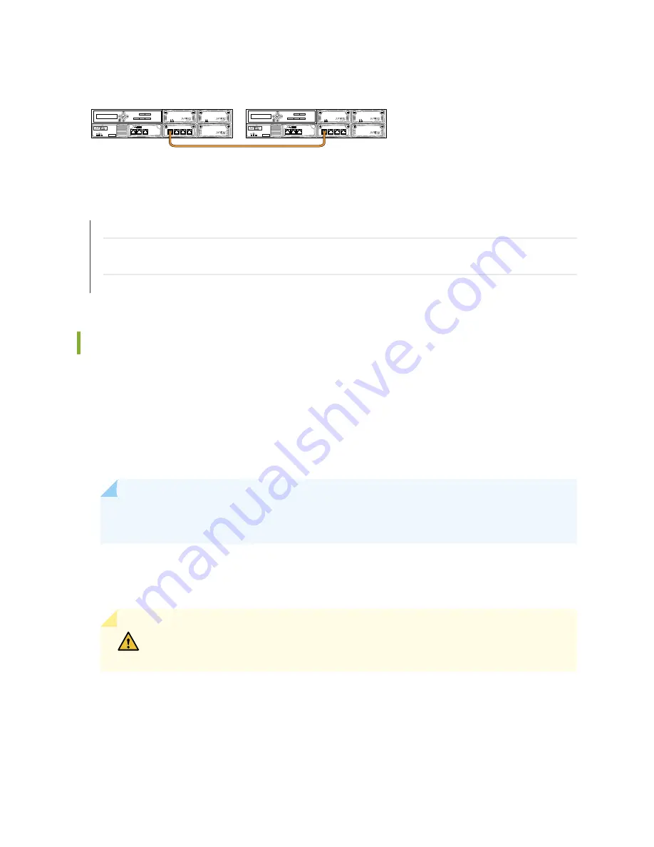
Figure 23: External Routing Engine to External Routing Engine Cabling
0
1
2
3
EX8200-XRE200
Disk Number
Slot Number
0
1
0
1
2
USB
LINK/
ACT SPD
CONSOLE
MGMT
0
LINK/
ACT SPD
LINK/
ACT SPD
LINK/
ACT SPD
LINK/
ACT SPD
0
1
2
3
EX8200-XRE200
Disk Number
Slot Number
0
1
0
1
2
USB
LINK/
ACT SPD
CONSOLE
MGMT
0
LINK/
ACT SPD
LINK/
ACT SPD
LINK/
ACT SPD
LINK/
ACT SPD
g020984
SEE ALSO
Connecting an EX8200 Switch to an XRE200 External Routing Engine | 84
Adding or Replacing a Member Switch or an External Routing Engine in an EX8200 Virtual Chassis (CLI
Procedure)
Configuring an EX8200 Virtual Chassis (CLI Procedure) | 87
Connecting AC Power to an XRE200 External Routing Engine
After you have installed an AC power supply in an XRE200 External Routing Engine, you connect the
external Routing Engine to AC power.
Before you begin connecting AC power to an XRE200 External Routing Engine:
•
Install the power supply in the chassis. See
“Installing an AC or DC Power Supply in an XRE200 External
NOTE:
Each power supply must be connected to a dedicated power source outlet to ensure
power supply redundancy.
Ensure that you have the following parts and tools available:
•
Power cords appropriate for your geographical location
CAUTION:
Mixing different types of power supplies in the same external Routing
Engine is not a supported configuration.
To connect AC power to an external Routing Engine:
1. Ensure that the power supplies are fully inserted in the external Routing Engine.
2. Insert the coupler end of the power cord into the AC power cord inlet on the AC power supply faceplate.
79
Summary of Contents for XRE200 -
Page 1: ...XRE200 External Routing Engine Hardware Guide Published 2020 12 15...
Page 135: ...135...
Page 142: ...142...
Page 155: ...Jewelry Removal Warning 155...
Page 158: ...Operating Temperature Warning 158...
Page 168: ...DC Power Disconnection Warning 168...
Page 172: ...DC Power Wiring Sequence Warning 172...


