background image

501

1

838

6 GB

E 22

3.6

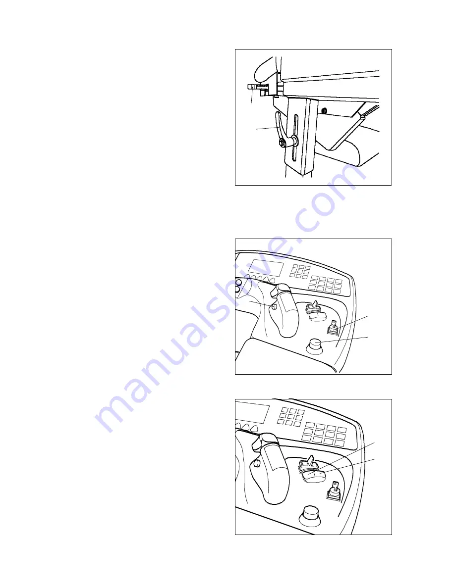
Adjusting the operating panel

The operating panel can be adjusted in
height and laterally.

Height adjustment:

– Simultaneously grip operating panel

and release lever (1).

– Adjust operating panel to correct

height and retighten lever.

Lateral adjustment:

– Pull lever (2) upward.
– Adjust operating panel to correct

position.

– Allow lever to latch again.

3.7

Providing operational readiness

– Turn and release EMERGENCY OFF

(6).

– Insert key into key switch (5) and turn

clockwise.

– Check proper function of warning

facility (horn) (7).

– Check proper function of service

brake and immobilising brake.

– Perform reference drive of lifting mast

for height indicator adjustment.

f

If any undesired travel or lifting motion
occurs, immediately actuate
EMERGENCY OFF switch.

3.8

Driver position adjustment

Driver seat with operating panel and
pedals can be continuously rotated
approx. 30° in load direction and approx.
10° in drive direction by push of a button.

– Setting toggle switch to position 3:

Driver position rotates to the right

– Set toggle switch to position 4: Driver

position rotates to the left

1

2

5

6

7

3

4

Summary of Contents for ETX ac 125

Page 1: ...Operating instructions 50118386 ETX ac 125 150 G 01 01 05 03...

Page 2: ...explanations are indicated by the following graphics f Used before safety instructions which must be observed to avoid danger to personnel m Used before notices which must be observed to avoid materi...

Page 3: ...0108 GB...

Page 4: ...s B 10 4 1 Truck identification plate B 11 4 2 Capacity B 11 C Transportation and commissioning 1 Transport C 1 2 Transportation by crane C 1 3 Commissioning C 2 3 1 Commissioning without battery C 2...

Page 5: ...the operating panel E 22 3 7 Providing operational readiness E 22 3 8 Driver position adjustment E 22 4 Operation of the truck E 23 4 1 Safety regulations applicable when operating the truck E 23 4 2...

Page 6: ...g the lifting chains F 10 6 4 Inspection of lifting chains F 11 6 5 Chain repair F 11 6 6 Changing gear oil F 11 6 7 Cleaning the aeration filter F 12 6 8 Changing the hydraulic filter F 12 6 9 Hydrau...

Page 7: ...50118386 GB I 4...

Page 8: ...in accordance with existing contractual agreements between the owner and the user of the fork lift truck is charged with the observance of the op erating duties The user must ensure that the truck is...

Page 9: ...A 2 50118386 GB...

Page 10: ...ipped with a rail guidance system RG or inductive guidance system IF The driver can fully concentrate on his stacking work Simultaneous travel and lifting is enables in narrow aisles The activation is...

Page 11: ...B 2 50118386 GB 2 Description of assembly groups and functions 1 2 3 4 5 6 7 9 10 11 12 8 17 16 15 14 13...

Page 12: ...ing frame 6 t Boom 7 t Fork arm carriage 8 o Storage location sensor 9 o Load sensor 10 o IG sensors only for inductive guidance 11 t Load wheel 12 o Guide rollers only for rail guidance 13 t Traction...

Page 13: ...teering angle is 90 providing excellent manoeuvrability in confined dead end aisles When the inductive guidance mode is used the steering is automatically taken over by the system and manual steering...

Page 14: ...and also for lifting and lowering The lifting height preselection system is designed for warehouse sections with different racking heights Hydraulic system All hydraulic movements are carried out by...

Page 15: ...signation ETX ac 125 ETX ac 150 Q Carrying capacity D 600 mm 1 250 1 500 kg D Load centre distance 600 600 mm Travel speed with without load RG inside the racking aisle 10 5 10 5 km h Lifting speed wi...

Page 16: ...B 7 50118386 GB...

Page 17: ...ll width 1 210 1 450 1 210 1 450 mm b5 Distance between forks outside 845 845 mm b6 Width across guide rollers depending on Ast mm l1 Overall width without load 3 492 3 780 mm l2 Length including back...

Page 18: ...compatibility EMC The manufacturer confirms compliance with the limit values for electromagnetic emission and interference immunity as well as testing of static electricity discharge according to prE...

Page 19: ...ic oil 3 Label Do not step on or under load danger of crushing 4 Label No passengers allowed 5 Label Observe operating instructions 6 Label capacity 7 Label crane hook 8 Label lifting point 9 Label Em...

Page 20: ...y in kg 21 Carrying capacity in kg 27 Year of manufacture 22 Battery Voltage in V Capacity in Ah 28 Type No 23 Manufacturer 29 Manufacturer s logo X xx xx xx xx xx Xxx Xxxx Xxxx Xxxx Xxxxxxx Xxxxxx Xx...

Page 21: ...B 12 50118386 GB...

Page 22: ...ly hoisting equipment with appropriated carrying capacity refer to the truck ID plate for truck weight see chapter B Observe additional battery weight Safe parking of the truck refer to chapter E With...

Page 23: ...protective cap 3 at the vent valve Slide hose 2 over the vent pipe and place the other end of the hose into the brake fluid container 1 located above f Brake fluid is under pressure Danger of caustic...

Page 24: ...ks are delivered with a tilting safety device 5 f this is prescribed in the order Before bringing commissioning the truck the tilting safety device must be reset to a distance of 10 to 12 mm to the gr...

Page 25: ...C 4 50118386 GB...

Page 26: ...nd cable shoes must be clean lightly greased with pole grease and must be securely tightened Batteries with bare terminal posts must be covered using a non skid insulating mat Disposal of the battery...

Page 27: ...off Unplug the battery plug If necessary remove the rubber insulating mat from the battery f As hazardous gases are produced during the charging operation sufficient fresh air supply must be ensured f...

Page 28: ...ust not be removed and their position not changed Turn key switch to O zero and push the EMERGENCY OFF Fully open the battery cover f Connecting and disconnecting the battery plug and socket is only p...

Page 29: ...bove the plates top edge Check the acid concentration according to the battery manufacturer s instructions using an acid pipette and screw in the plugs again when finished If required recharge the bat...

Page 30: ...truck or on the attachments must immediately be brought to the notice of the person in charge fork lift trucks that cannot be safely operated e g due to worn tyres or defective brakes must not be used...

Page 31: ...ng seat switch t To turn driver seat 7 Key switch t Switches control voltage on and off 8 Emergency OFF switch t The power circuits are interrupted all electrical functions switch off 9 Hydraulics con...

Page 32: ...Brake pedal t Actuates the load wheel brake 15 Dead man pushbutton foot operated switch t Disengage the immobilising brake When actuated disengages the spring loaded brake and releases the travel moti...

Page 33: ...isplay element Function 10 Pushbutton Quit submenu t Sets the menu from swivel traverse to basic display 11 Display of possible travel speed Snail Rabbit t Inching Maximum speed 12 Display Guide wire...

Page 34: ...ting hours since first putting into service 16 Display Time of day t Displays the time of day 17 Battery discharge indicator t Shows the charging condition of the battery remaining capacity in percent...

Page 35: ...ic height dependent drive cut off has been activated Pushbutton Override drive cut off Overrides the automatic height dependent drive cut off Display End of aisle safety device optional o Indicates th...

Page 36: ...uency 1 Pushbutton Select frequency 1 and other frequencies in the same way Activates guidance via frequency 1 automatic exit from submenu after pushing for 1 second Fork operation Display Toggle menu...

Page 37: ...nob Display Automatic synchronous turn to fork centre position Indicates that automatic positioning of the fork in centre position fork arms to the front is possible Pushbutton Automatic synchronous t...

Page 38: ...perated Pushbutton Symmetrical fork arm adjustment Activates fork arm adjustment for simultaneous operation of the hydraulics control knob Turn right fork arms to inside turn right fork arms to outsid...

Page 39: ...Stack cycle enabled fork right without load Stack cycle enabled fork left with load Stack cycle enabled fork left without load Lifting enabled fork left with load Lowering enabled fork left with load...

Page 40: ...d right Fork 90 extended left Fork 90 extended right Fork 0 extended left Fork 0 extended right Fork between 0 90 left transport position left Fork between 0 90 right transport position right Fork 90...

Page 41: ...direction and antenna centre Field detected Antenna drive direction Field detected Actuate foot switch Reference drive lowering Reference drive completed height indication Reference drive lifting Wor...

Page 42: ...rsonnel protection facility active flashing not active Personnel protection facility forced braking acknowledge not required Traversing telescopic fork Side shift Fork front position Load carrying uni...

Page 43: ...cator 2 Stacking depth End of aisle safety device override Zone 1 to zone 7 Clamp menu button Open clamp Close clamp Travel direction indicator drive direction Travel direction indicator load directio...

Page 44: ...E 15 50118386 GB Display symbol assignment...

Page 45: ...50118386 GB E 16 Display symbol assignment Time of day Height display Operating hours...

Page 46: ...ay the control system enables all movements of the truck at full speed and the height preselection is adjusted Lifting and lowering is indicated by the symbols Reference drive lifting Reference drive...

Page 47: ...he fork arms out to the side Check load wheels for damages Check whether the load chains are tensioned uniformly Check whether all safety devices are operational and function properly For rail guided...

Page 48: ...row direction until the corresponding weight is indicated on the driver seat weight display 12 and guide the setting lever back again Sit on the driver seat Adjusting the backrest Pull up the backrest...

Page 49: ...to the restraint belt are not permitted Increased risk through malfunctions Replace restraint belts after an accident Use only original spare parts for retrofits and repairs f Damaged or non functioni...

Page 50: ...ing retractor allows sufficient freedom of shifting around on the seat f When sitting on the front edge of the seat the belt is rolled out too long thus providing not enough protection A Only use the...

Page 51: ...switch 5 and turn clockwise Check proper function of warning facility horn 7 Check proper function of service brake and immobilising brake Perform reference drive of lifting mast for height indicator...

Page 52: ...equate braking distance between the truck and the vehicle in front and he must be in control of his truck at all times Sudden stopping except in emergencies rapid U turns and overtaking at dangerous o...

Page 53: ...clear of any obstacles The floor surface must be clean in order to achieve sufficient traction If a narrow aisle is equipped with inductive guidance and the guidance system is defective or switched of...

Page 54: ...is travelling in For travel operation the foot switch must be constantly pressed Releasing the foot switch will initiate forced braking Driving on the front yard f The travel paths must be free of ob...

Page 55: ...ing to the opposite travel direction Braking by means of brake pedal By actuating the brake pedal the truck is decelerated by means of the hydraulic show brake in the load wheels The intensity of dece...

Page 56: ...ust be stopped immediately A Driving into narrow aisles is only allowed with trucks that have been designed for this operation If a narrow aisle is equipped with a mechanical guidance system and the g...

Page 57: ...ection might break out of line under certain circumstances if the front sensor 3 has already crossed the guide wire before the button Inductive guidance ON has been pushed Drive the truck 1 diagonally...

Page 58: ...n signal is no longer sounded The truck is now force guided The maximum travel speed is enabled To leave the guide wire the pushbutton 23 for inductive forced steering must be actuated f Switching ove...

Page 59: ...A The lifting and lowering speed is proportional to turning the hydraulic control knob The maximum lifting speed is achieved when carrying position swivel traverse is indicated in the display A Lower...

Page 60: ...rsonnel is allowed in the danger zone when swivelling shifting or synchronous turning the load carrying unit A When shifting the load carrying unit the fork arm carriage is swivelled The turning speed...

Page 61: ...ersing to the left A The traversing speed is proportional to turning the hydraulic control knob The telescopic fork is automatically stopped in centre position After releasing the hydraulic control kn...

Page 62: ...load Release foot switch Fully lower the load carrying unit respectively lift to the proper height with respect to the load so that the fork arms can be inserted under the load without damaging it f L...

Page 63: ...d until it makes contact with the back of the fork f The fork arms must be inserted into the load with their full length Release foot switch Lift the swivel traverse fork slightly so that the load is...

Page 64: ...unit Pick up or set down the load refer to section Picking up a load sideways respectively Setting down a load f Special care must be taken when working at the first rack shelves as the truck is part...

Page 65: ...load carrying unit out of the load Fully lower the load carrying unit 4 5 Lifting height preselection To pick up or set down loads at preselected storage locations the truck must be adjusted to the wa...

Page 66: ...nob is no longer pushed the work cycle is cancelled 4 It is only necessary to push the hydraulic control knob during traversing of the fork carrier after that the stacking cycle runs automatically unt...

Page 67: ...when the laser beam of a light hits the marking on the rack m Laser beam Do not look into the beam Laser Class 2 4 7 Safe parking of the truck When the truck is left it must be parked in a secure mann...

Page 68: ...charge recharge battery if required Foot switch not actuated Actuate foot switch Drive cut off has been triggered Actuate pushbutton Override drive cut off Drive cut off by aisle protection Switch of...

Page 69: ...that the continuation of travel is possible at inching speed by pushing the override button continuously A The pushbutton for drive cut off is located in the control panel 6 3 Lift cut off with overr...

Page 70: ...continue the travel Briefly release foot switch and step down again The vehicle can be driven out of the narrow aisle at max 2 5 km h 2 Deceleration to recommended maximum speed When crossing the end...

Page 71: ...functioning of the front and lateral stacking truck by means of manual steering and inductive forced steering f If the fault could not be cleared by these two measures authorised service personnel mu...

Page 72: ...ontainer After reconnecting the power and repeated actuation of the foot switch the brake system is fully operational again Disengaging the solenoid brake Remove the cover from the rear electronic com...

Page 73: ...50118386 GB E 44...

Page 74: ...rained especially for these assignments We thus recommend signing a maintenance contract with the relevant service location of the manufacturer Lifting and jacking up When a fork lift truck is to be l...

Page 75: ...nd the driving behaviour of the fork lift truck The factory mounted tyres must only be replaced by original spare parts of the manufacturer since otherwise the specification of the data sheet cannot b...

Page 76: ...eek M3 every 500 operating hours but at least every 3 months M6 every 1000 operating hours but at least every 6 months M12 every 2000 operating hours but at least every 12 months In the running in pha...

Page 77: ...unction and damage t Drive 2 1 Grease the bearing of the transmission t 2 2 Check transmission for noise and leaks t 2 3 Check the transmission oil level t 2 4 Change transmission oil t Wheels 3 1 Che...

Page 78: ...leaks and damages a t Electr system 7 1 Check the discharge of static charges t 7 2 Performance check t 7 3 Check cables for secure connection and damage t 7 4 Check cable guides for function and dam...

Page 79: ...stops for wear and damage clean and grease also grease the toothed racks t 11 4 Check eccentric bolt and glide bar adjustment at swivel traverse frame and re adjust if necessary t 11 5 Grease guide r...

Page 80: ...F 7 50118386 GB 4 Lubrication schedule Lubricator nipple Outer lifting mast Load carrying unit Centre lifting mast Boom Inner lifting mast Drive system...

Page 81: ...50118386 GB F 8 g Glide surfaces s Lubricator nipples...

Page 82: ...nsumption type materials of different grades or qualities resp except if mixing is expressively prescribed in these operating instructions Avoid spilling Spilt liquid must be removed immediately using...

Page 83: ...commissioning have to be observed refer to chapter C 6 2 Secure the load carrying unit The load carrying unit can be secured in elevated position Lift the load carrying unit until the inner mast 1 is...

Page 84: ...ng chains only original parts may be used The rivet heads must be ground off before dismounting In this way damages caused by driving the bolt through the intermediate plate resp the inner link in the...

Page 85: ...an with compressed air or cleaning agent m Waste filters must be disposed of properly 6 8 Changing the hydraulic filter Unscrew hydraulic filter cap 9 Change the filter insert if the O ring is damaged...

Page 86: ...ter 8 If this method cannot be used the hydraulic oil can be drained after unscrewing the oil drain plug at the bottom of the hydraulic tank Refilling oil Screw in the oil drain plug again Fill in new...

Page 87: ...em has no leaks 6 11 Restrain safety belt service The driver must check condition and correct operation of the safety restraint belt on daily basis before using the industrial truck Early detection of...

Page 88: ...ditional measures must be discussed with the Service Department of the manufacturer 7 1 Operations to be performed prior to decommissioning Thoroughly clean the fork lift truck Check the brakes for co...

Page 89: ...hecked by a qualified inspector The inspector must assess the condition of the truck from a standpoint purely concerned with safety aspects uninfluenced by any company or economic circumstances The in...

Reviews: