background image


29 

12.7


MDO Operation mode 

If the CNTL parameter is set in the 

Common Parameter

  menu as S/P (speed/Position), P/T 

(Position/Torque), or S/T (Speed/Torque) mode, this input signal enables the switching between operation 

modes. 

For example: If CNTL is set as S/P mode, when CN-34 and 24G is not connected, the servo drive is 

in Speed operation mode, when connected; the servo drive is switched to Position operation mode. 
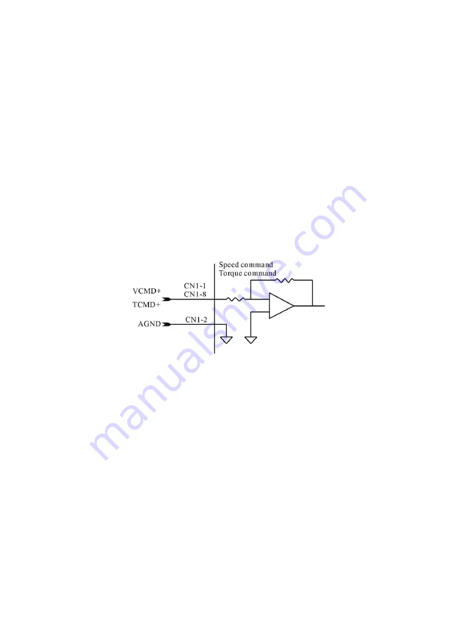
 

12.8


VCMD+ and TCMD+ inputs (CN1-1 and CN1-8) 

VCMD+: When the servo drive is in S Mode or is switched to S mode, this signal is used as analog 

speed command input. The input voltage scale can be modified at the VMDL parameter contained in the 

Speed Parameter

  menu. The value of the VMDL parameter defines the input voltage which 

corresponds to the rated speed, with positive voltage for forward rotation, and negative voltage for reverse 

rotation. 

TCMD+: When the servo drive is in T Mode or is switched to Torque operation mode, this signal is 

used as analog torque command input. If the input voltage is 10V, the motor outputs 300% of the rated 

torque. 


Note: CN1-1 is for high-resolution analog signal input (12 BIT). Please purchase YPV-XXX-V series 

servo drive if high-resolution analog input is needed. The input pin of the standard analog input 

(resolution 10 BIT) is CN1-8. 

Summary of Contents for YPV-040

Page 1: ...Manual V2 1 JS AUTOMATION CORP 100 6 6F No 100 Zhongxing Rd Xizhi Dist New Taipei City Taiwan TEL 886 2 2647 6936 FAX 886 2 2647 6940 http www automation com tw http www automation js com E mail contr...

Page 2: ...ver 3 Modify description of CN1 Pin16 Hold 1 3 1 Chapter 5 I O Signal Definitions and CN1 Pin Assignments Pin5 6 7 13 14 15 16 30 31 34 descriptions rewrite for more detail Pin1 2 description rewrite...

Page 3: ...Signal waveform of feedback Encoder 16 6 Position command input circuit 17 6 1 From differential type line driver 17 6 2 From open collector output 17 7 Analog command input circuit 18 7 1 Analog comm...

Page 4: ...7 MON1 MON2 Analog monitor outputs CN1 11 12 35 13 8 Encoder output signals CN1 19 24 35 14 User parameter settings and functions 36 14 1 Parameter settings and functions 36 15 Driver setup via PC com...

Page 5: ...itation of the liability of JS automation Corp will apply regardless of the form of action whether in contract or tort including negligence Any action against JS automation Corp must be brought within...

Page 6: ...nd encoder specification are the same as the ordered 4 In the case of special order please carefully check the delivered products and contact our company immediately if any item is incorrect The table...

Page 7: ...Power cable connector M Water proof L model N Water proof V model Servo drive Model Serial Number Servo drive Specification Version 1 2 Servomotor model YBL13S75 L Z Servomotor Serial Number Servomoto...

Page 8: ...V 300 V Servodrive Capacity 040 0 4 KW 600 6 KW 055 0 55 KW 750 7 5 KW 075 0 75 KW 860 8 6 KW 100 1 KW 1100 11 KW 150 1 5 KW 1500 15 KW 200 2 KW 2200 22 KW 300 3 KW 3000 30 KW 450 4 5 KW Type V High r...

Page 9: ...AC mains input 3 220Vac E Ground Terminal must be connected to prevent electrical shock UVW Servomotor Cable Terminal B1 B2 Brake Resistance Terminal H1 H2 Servomotor Thermostat Terminal CN3 Communica...

Page 10: ...servo drives side by side as shown in the figure below allow at least 50mm above and below each servo drive or install cooling fans to facilitate air circulation Servo drive Installation and Cooling...

Page 11: ...mm for maintenance space In addition to ensure the reliability and improve the product life leave certain distance between the servo drive and the cabinet ceiling so the temperature around the servo d...

Page 12: ...der stress Be cautious of the cable wiring to avoid as much as possible being subject to bending or tension 4 If the servomotor is moving with the mechanism arrange the bending section of the cable li...

Page 13: ...ontrol mode If not using the line driver type the PULSE GND must be connected to DGND or the lost pulse fault may occur C A U T I O N 1 Do not bundle power and signal lines together in the same duct L...

Page 14: ...water from entering via the cable line 3 Carefully avoid the exposure of cable lines to oil and water that have adverse effects on servomotor and encoder also may cause malfunctions of the servo drive...

Page 15: ...s attached with a magnetic brake either horizontal or vertical installation is allowed When the shaft is upward installed the brake may normally make some noise 4 3 Alignment Align the shaft of the se...

Page 16: ...t to water or oil mist Also use a servomotor with an oil seal to seal the through shaft section 4 5 Cable stress Make sure there are no bends or tension on the power lines Be especially careful to sig...

Page 17: ...2 White Grey A 2 3 Gray B 3 4 White Gray B 4 5 Yellow C 5 6 White Yellow C 6 7 Brown U 7 8 White Brown U 8 9 Orange W 9 10 White Orange W 10 11 Blue V 11 12 White Blue V 12 13 Red 5V 13 14 White Red...

Page 18: ...erential type line driver 6 2 From open collector output Example 1 Using an external power supply provided by the user Note Mokon Servo drive can be only connected with 24V external power supply Examp...

Page 19: ...18 7 Analog command input circuit 7 1 Analog command input circuit 7 2 Digital input circuit interface...

Page 20: ...19 8 Output interface circuits 8 1 Digital output interface Example 1 Connecting to a relay output circuit Example 2 Connecting to a photo coupler output circuit...

Page 21: ...20 8 2 Encoder digital output interface circuit...

Page 22: ...21 9 Position control interface...

Page 23: ...22 10 Speed control interface...

Page 24: ...23 11 Torque control interface...

Page 25: ...ected with 24G internal 24V pull high NRIH 15 Reverse Rotation Inhibited Digital signal for inhibiting the reverse rotation when connected with 24G internal 24V pull high HOLD OR PI P 16 Motor HOLD fo...

Page 26: ...responds to reverse rotation pin8 can also act as low resolution speed command input AGND 2 Analog ground Analog signal ground TORQUE TCMD 1 Torque command During driver set at torque mode Enables the...

Page 27: ...rse rotation pulse Input CCW Dir B NPCMD 29 Reverse rotation pulse Input Reverse rotation pulse Input CCW Dir B Common Signal for Position and Speed Command EG1 SPD 32 Electronic gear 1 Speed selectio...

Page 28: ...stop signal 12 3 RST Servo reset input CN1 7 This signal is used to reset the servo drive after clearing the servo alarm 12 4 TLM Torque limit input CN1 13 This signal together with the TLCMD analog v...

Page 29: ...control mode switch input CN1 16 If Motor Hold function is selected the servomotor will be stopped and held still when CN1 16 is connected with 24G The servomotor is decelerated according to the progr...

Page 30: ...as analog speed command input The input voltage scale can be modified at the VMDL parameter contained in the Speed Parameter menu The value of the VMDL parameter defines the input voltage which corre...

Page 31: ...he motor 12 10 PPCMD PPCMD NPCMD NPCMD Position command inputs CN1 26 29 When the servo drive is in P Mode or switched to Position operation mode these signals are used as position command inputs The...

Page 32: ...ent internal speed commands which are defined by the parameters Internal Speed 1 Internal Speed 2 and Internal Speed 3 Unit RPM in the Speed Parameter menu When the servo drive is in P Mode or switche...

Page 33: ...value in torque is saturated at the torque limit value in torque operation mode Speed Position Common Signal INP INS 18 Position Speed Arrival Digital signal output for indicating the value of positio...

Page 34: ...arameter menu If CN 17 is programmed as the servo ready signal default after the driver is enabled and no alarm has been detected the servo ready signal will be issued immediately When the system powe...

Page 35: ...et by the driver CN1 37 will be connected with 24G to issue the In Torque Limit signal 13 6 INS INP Speed Position arrival output CN1 18 If the servo drive is set as S Mode when the motor speed is equ...

Page 36: ...he scale offset and resolution of the output signals are also defined MON1 as Monitor Channel A defined the Common Parameter menu MON2 as Monitor Channel B defined the Common Parameter menu 13 8 Encod...

Page 37: ...que mode S P T 3 0 5 2 PMOD PULSE CMD TYPE 0 PULSE DIR 1 A B 2 CW CCW Note no valid for YPV ver 2 P 0 0 2 3 Ta acceleration time for speed mode linear acceleration profile Note internal generated prof...

Page 38: ...nternal speed generator disable 1 internal speed generator enable S 0 0 1 9 SPD1 speed1 of internal speed generator Note selected by SPD1 digital input while SP0 1 S 500 RPM rated RPM rated RPM 10 SPD...

Page 39: ...0 17 TLCS torque limit source 0 internal 1 external analog command voltage from CN1 9 S P 1 0 1 R W 18 TQCA filter time constant for torque command input Note Larger time constant will decrease the ba...

Page 40: ...32 ELGN numerator of gear ratio P 10 1 30000 33 ELGN1 numerator 1of gear ratio selected by EG1 digital input P 10 1 30000 34 ELGN2 numerator 2 of gear ratio selected by EG2 digital input P 100 1 30000...

Page 41: ...rate discharge duty cycle 50 0 100 48 POEN Numerator of encoder output ratio 1 32767 49 POED Denominator of encoder output ratio 1 32767 50 IMON Real time current value for monitoring ma RO 51 SMON Re...

Page 42: ...nsation switch S P 0 0 1 61 not available 62 TSLO speed limit source of torque mode 0 internal 1 external analog voltage in T 0 0 1 R W 63 not available 64 DILS polarity of over travel limit input CN1...

Page 43: ...lick the mouse on my computer icon Choose the Properties item 2 Select Hardware Device manager 3 Select Ports COM LPT and choose the com port you are connecting to 4 Select Port Settings to change par...

Page 44: ...left shows the display of ComPort Setting please choose the Communication Port used by your computer first 15 3 Basic functions Mokon Servo drive has the following five menus for parameter setting 1 C...

Page 45: ...MDO S Mode Speed mode which is a single mode and cannot be switched through CN1 34 MDO P Mode Position mode which is a single mode and cannot be switched through CN1 34 MDO S P Mode Speed Position mod...

Page 46: ...45 Electromagnetic brake release time MBR MBR is effective only when CN1 17 is programmed as the Motor Brake Release function Available range 0 1000 ms Monitor voltage MOVL...

Page 47: ...age corresponds to the motor rated speed If I Monitoring is selected the maximum output voltage corresponds to the motor 300 rated current If P Monitoring is selected the maximum output voltage corres...

Page 48: ...ou can choose CN1 17 as Servo Ready output CN1 17 will be closed immediately when the servo drive is turned on and turn off when an alarm has been detected to signal the controller Electromagnetic bra...

Page 49: ...signal is issued Logic for positive and negative limit Logic for positive and negative limit Define the input logic of CN1 14 Forward Positive Rotation Inhibited PRIH and CN1 15 Reverse Negative Rotat...

Page 50: ...ained in the servo drive after the power is turned off Upload and Program After entering the parameters it is necessary to press this button to write these parameters stored in the registers onto the...

Page 51: ...SPDO Allowable range 1024 1024 mV Used to compensate for the offset of the voltage command Set the offset voltage according to the actual condition and the desired speed command is obtained internall...

Page 52: ...first internal speed CN1 33 the second internal speed and CN1 35 the third internal speed in the speed operation mode 1st Internal Speed Settings 2nd Internal Speed Settings 3rd Internal Speed Setting...

Page 53: ...leration deceleration time to 0 Before setting S type acceleration deceleration time linear acceleration deceleration time must be set otherwise the characteristics of S type acceleration deceleration...

Page 54: ...vo drive can accept the following three types of command Filter frequency Filter frequency is only valid if the Command type is selected as A B WITH FILTER Pulse command trigger type To select the pol...

Page 55: ...on X 4 10000 Numerator 5000 Denominator Numerator1 Under the position operation Mode Numerator 1 will be selected as the numerator of the electronic gear ratio when CN1 32 is connected with 24G Numera...

Page 56: ...the incoming encoder signal or inverse with the incoming Choose Standard means the same phase inverse means inverse phase Encoder input filter frequency The digital filter of the input encoder signal...

Page 57: ...red if the time constant is small response will be fast but noise may come into system large filter time constant will filter out high speed command or noise Percent of torque limitation Range availab...

Page 58: ...torque speed limit choose this option the CN1 8 speed input will be the speed limit of torque command CN1 1 Torque limit command option There are 2 type of torque limit 3 Internal torque limit choose...

Page 59: ...ations Max current the 3 rated current of servo motor less is possible but will limit the motor instantaneous torque Driver Protection Setting Discharge Duty Cycle use 50 as regular condition Over Spe...

Page 60: ...Speed Loop Gain 1 2 Speed Loop Gain 2 3 Monitor 4 Unit Conversion 15 10 Speed Loop Gain 1 The KVI KVP of speed loop gain1 is used as the speed is higher than SSPD setting value KVI Speed loop integral...

Page 61: ...dynamic response of the speed loop and is the proportional gain of the speed compensator This parameter should be tuned properly according to the load inertia and the larger the KVI parameter is tune...

Page 62: ...ith CH3 in the oscilloscope Slowly adjust the KVP parameter in the Speed Parameter menu The adjustment should not stop until the rising slope of the S Monitor signal is close enough to the speed comma...

Page 63: ...62 15 12 Online Monitor Use Read button to read the under monitoring data and stop to exit...

Page 64: ...stop Check the reason of overload 4 OH The temperature over 135 in the servomotor winding or over 85 in the heat sink of the servo drive triggers the OH alarm The machine will stop Check the ambient t...

Page 65: ...red black brown White brown orange White orange blue White blue shielding NC A A B B C C 5V 0V U U W W V V D 15P 1 2 3 4 5 6 13 14 15 7 8 9 10 11 12 case 2E20 29P and D 15P Pin Table 2E20 29P A B C D...

Page 66: ...nsion Dimension mm Weight kg Model A B D E W H YPV 040 YPV 055 YPV 075 YPV 100 30 23 212 195 90 168 1 9 YPV 150 30 23 212 195 106 168 2 5 YPV 200 YPV 300 YPV 450 30 23 256 239 106 168 3 4 YPV 600 30 3...

Page 67: ...Weight kg Model W W1 W3 H H1 H2 h1 h2 D0 D1 D2 d d1 YPV 750 YPV 860 YPV 1100 YPV 1500 270 253 235 460 445 429 7 5 2 5 300 100 185 10 2 3 18 6 19 5 YPV 2200 YPV 3000 440 419 275 685 660 629 5 15 30 36...

Page 68: ...el Motor Wattage Resistance Ohm Power Rating 400W 100 80 550W 1KW 100 80 1 5KW 2KW 60 150 3KW 60 150 4 5KW 30 300 6KW 30 300 8 6KW 15 600 11KW 10 800 15KW 5 1500 22KW 5 1500 30KW 2 5 3000 The resistan...

Page 69: ...68 20 Wiring of MPC3024 wiring board to Mokon driver...

Page 70: ...PF alarm The machine will stop Check whether the AC Mains voltage is too low or the filtering capacitor in the main circuit is damaged Use 3 AC power for the servo drive over 550W b FO Fuse open Fuse...

Reviews: