background image

SECTION 3 - TROUBLESHOOTING

3121804

– JLG Lift –

3-9

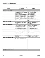
No voltage present at function control switch

Check wiring from power switch to function control 
switch for proper connection or damage. Repair or 
replace wiring as necessary

Defective function control switch

Replace function control switch

No voltage present at applicable control valve coil Check applicable wire for proper connection at 

terminal strip, valve harness plug pin, valve har-
ness receptacle pin and valve coil. Using suitable 
test meter, perform continuity test on wire. Repair 
or replace harness as necessary

No voltage supplied to motor from start relay

Check battery cable from relay to motor for proper 
connection or damage. Repair or replace cable as 
necessary

Defective motor/pump assembly

Replace motor/pump assembly

ENGINE STARTER SYSTEM

Engine will not crank

Discharged battery or loose battery terminals

Check and charge battery or replace battery as 
necessary. Clean and secure battery terminals

Starter relay faulty or faulty relay connections

Using a test meter, check relay coil terminals for 
presence of electrical power and for energization 
of relay coil. Also check relay terminals for correct 
switching of contacts. Replace relay as necessary

Malfunctioning starter solenoid or motor

Replace solenoid or motor in accordance with 
applicable manufacturer’s manual

Defective start lockout solenoid

Replace start lockout solenoid

Malfunctioning ignition switch

Using a test meter, check ignition switch for cor-
rect switching of contacts. replace switch as nec-
essary

Faulty ignition and/or starter circuit wiring

Check wiring continuity. refer to wiring diagram

Defective ring gear or flywheel

Replace ring gear

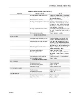
INSTRUMENTS AND INDICATORS

Ammeter inoperative

Damaged wiring in circuits

Repair or replace wiring

Ammeter not functioning properly

Replace ammeter

Alternator not charging

Repair or replace alternator

Travel warning horn inoperative

Circuit breaker open

Determine and correct cause

Damaged wiring in horn circuit

Replace horn

Hourmeter inoperative

Damaged wiring in hourmeter circuit

Repair or replace wiring

Inoperative hourmeter

Replace hourmeter

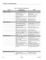
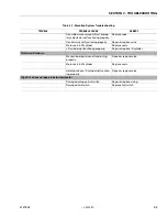
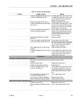
Table 3-4. Electrical System Troubleshooting

TROUBLE

PROBABLE CAUSE

REMEDY

Summary of Contents for 330CRT

Page 1: ...Service Maintenance Manual Model 330CRT 400CRT 3121804 April 7 2004 ...

Page 2: ......

Page 3: ... should be noted that the machines hydraulic sys tems operate at extremely high potentially danger ous pressures Every effort should be made to relieve any system pressure prior to disconnecting or removing any portion of the system Relieve system pressure by cycling the applicable control several times with the engine stopped and ignition on to direct any line pressure back into the reservoir Pre...

Page 4: ...INTRODUCTION MAINTENANCE SAFETY PRECAUTIONS b JLG Lift 3121804 REVISON LOG Original Issue April 13 2000 Revised August 17 2000 Revised September 28 2001 Revised October 18 2002 Revised April 7 2004 ...

Page 5: ...aintenance Guidelines 2 1 2 3 Lubrication Information 2 2 2 4 Cylinders Theory of Operation 2 3 2 5 Valves Theory of Operation 2 3 2 6 Component Functional Description 2 4 2 7 Wear Pads 2 4 2 8 Cylinder Checking Procedures 2 4 2 9 Lift Cylinder Removal and Installation 2 5 2 10 Lift Cylinder Repair 2 9 2 11 Steer Cylinder Repair 2 14 2 12 Oscillation Cylinder Bleeding 2 16 2 13 Magnetic Speed Pick...

Page 6: ... 10 Installation of Head Seal Kit 2 11 2 11 Piston Seal Kit Installation 2 12 2 12 Tapered Bushing Installation 2 12 2 13 Seating the Tapered Bearing 2 12 2 14 Poly Pak Piston Seal Installation 2 13 2 15 Rod Assembly Installation 2 13 2 16 Steer Cylinder Assembly 2 14 2 17 Magnetic Speed Pickup 2 16 2 18 Magnetic Speed Pickup Removal 2 16 2 19 Valve Components 2 17 2 20 Automatic Choke Adjustment ...

Page 7: ...Stability Weights 1 6 2 1 Cylinder Component Torque 2 13 2 2 Holding Valve Torque Specifications 2 13 2 3 Help Messages and Flash Codes 2 21 2 4 Machine Model Adjustment 2 25 2 5 Machine Configuration Programming Information 2 26 2 6 Preventive Maintenance and Safety Inspection 2 28 3 1 Elevation System Troubleshooting 3 2 3 2 Chassis Troubleshooting 3 4 3 3 Hydraulic System Troubleshooting 3 7 3 ...

Page 8: ...TABLE OF CONTENTS iv JLG Lift 3121804 This page left blank intentionally ...

Page 9: ...0 F Fuel Consumption Low RPM 4 9 lph 1 3 gph High RPM 9 lph 2 4 gph Horsepower 24 5 3600 RPM Diesel Engine Manufacturer Kubota 1105 Low RPM 1500 High RPM 3000 Alternator 40 Amp Battery 85 Amphour 700 cold cranking amps 17 8 C 0 F Fuel Consumption Low RPM 3 5 lph 93 gph High RPM 6 6 lph 1 7 gph 21 kW 3000 RPM 28 Horsepower 3000 RPM Drive Steer System Toe In Adjust to 12 7 mm 1 2 inch overall Drive ...

Page 10: ...osity index of152 NOTE Aside from JLG recommendations it is not advisable to mix oils of different brands or types as they may not contain the same required additives or be of comparable viscosities If use of hydraulic oil other than Mobilfluid 424 is desired contact JLG Indus tries for proper recommendations Lubrication Specifications Table 1 1 Hydraulic Oil HYDRAULICSYSTEMOPERATING TEMPERATURERA...

Page 11: ...be HO Hydraulic Oil Mobil 424 TO AVOID PERSONAL INJURY USE SAFETY PROP FOR ALL MAINTENANCE REQUIRING PLATFORM TO BE ELEVATED NOTE Be sure to lubricate like items on each side NOTE Recommended lubricating intervals are based on machine operations under normal conditions For machines used in multi shift operations and or exposed to hostile environments or conditions lubri cation frequencies must be ...

Page 12: ...SECTION 1 SPECIFICATIONS 1 4 JLG Lift 3121804 Figure 1 1 Torque Chart ...

Page 13: ...he serial number plate be damaged or missing the machine serial number is stamped on the top of frame between the front wheels 1 8 LIMIT SWITCHES The machine is equipped with the following limit switches High Drive Speed Cut Out High drive speed is cut out when platform is raised above stowed fully lowered posi tion Tilt Alarm 3 A horn is sounded and a warning light is illuminated when the machine...

Page 14: ...ke RodDia LiftCylinder 330CRT 4 0 10 2 63 7 161 8 2 75 7 0 UpperLiftCylinder 400CRT 3 0 7 62 58 1 147 6 2 75 7 0 LowerLiftCylinder 400CRT 4 0 10 2 58 1 147 6 2 75 7 0 LockoutCylinder OscillatingAxle 3 0 7 6 3 75 9 5 1 25 3 2 LevelingJack Cylinder 2 0 5 1 14 0 35 6 1 25 3 2 SteerCylinder 2 5 6 4 7 1 18 1 1 25 3 2 Table 1 5 Major Component Weights Component Lb Kg FixedPlatform 569 258 PlatformExtens...

Page 15: ...duled basis in order to function properly 2 At any time when air fuel or oil lines are discon nected clear adjacent areas as well as the openings and fittings themselves As soon as a line or compo nent is disconnected cap or cover all openings to prevent entry of foreign matter 3 Clean and inspect all parts during servicing or main tenance and assure that all passages and openings are unobstructed...

Page 16: ... at the specified intervals When recommended lubricants are not available consult your local supplier for an equivalent that meets or exceeds the specifications listed Batteries Clean batteries using a non metallic brush and a solution of baking soda and water Rinse with clean water After cleaning thoroughly dry batteries and coat terminals with an anti corrosion compound Lubrication and Servicing...

Page 17: ...ts as recommended by the component manufacturers are always the best choice however multi purpose greases usually have the qualities which meet a variety of single purpose grease requirements Should any question arise regarding the use of greases in maintenance stock consult your local supplier for evalua tion 2 4 CYLINDERS THEORY OF OPERATION Cylinders are of the double acting type The Lift and S...

Page 18: ...ief Valves Crossover relief valves are used in circuits where the actu ator requires an operating pressure lower than that sup plied to the system When the circuit is activated and the required pressure at the actuator is developed the cross over relief diverts excess pump flow to the reservoir Indi vidual integral reliefs are provided for each side of the circuit 2 6 COMPONENT FUNCTIONAL DESCRIPT...

Page 19: ...om the ports If leakage continues at a rate of 6 8 drops per minute or more the counterbalance valve is defective and must be replaced 5 If no repairs are necessary or when repairs have been made carefully reconnect hydraulic hoses to the appropriate ports 6 Remove lifting device from platform activate hydrau lic system and run cylinder through one complete cycle to check for leaks 2 9 LIFT CYLIND...

Page 20: ...SECTION 2 PROCEDURES 2 6 JLG Lift 3121804 Figure 2 1 Arms and Platform Positioning and Support Cylinder Repair ...

Page 21: ...e piston end into the barrel cylinder Ensure that the piston loading o ring and seal ring are not damaged or dislodged 9 Continue pushing the rod into the barrel until the cyl inder head gland can be inserted into the barrel cyl inder 10 If applicable secure the cylinder head retainer using a suitable chain wrench 11 After the cylinder has been reassembled the rod should be pushed all the way in f...

Page 22: ...SECTION 2 PROCEDURES 2 8 JLG Lift 3121804 Figure 2 3 400CRT LIft Cylinder ...

Page 23: ...sy realignment Using an allen wrench loosen the cylinder head retainer cap screws and remove cap screws from cylinder barrel 6 Using a spanner wrench loosen the end cap or head retainer and remove from cylinder barrel 7 Attach a suitable pulling device to the cylinder rod port block end or cylinder rod end as applicable IMPORT ANT EXTREME CARE SHOULD BE TAKEN WHEN REMOVING THE CYL INDER ROD HEAD A...

Page 24: ...for damage Dress threads as necessary 8 Inspect seal and o ring grooves in piston for burrs and sharp edges Dress applicable surfaces as nec essary 9 Inspect cylinder head inside diameter for scoring or other damage and for ovality and tapering Replace as necessary 10 Inspect threaded portion of head for damage Dress threads as necessary 11 Inspect seal and o ring grooves in head for burrs and sha...

Page 25: ...e Install a new wear ring into the applicable cylinder head gland groove 3 Place a new o ring and back up seal in the applica ble outside diameter groove of the cylinder head 4 Install washer ring onto rod carefully install the head gland on the rod ensuring that the wiper and rod seals are not damaged or dislodged Push the head along the rod to the rod end as applicable 5 Carefully slide the pist...

Page 26: ... and insert JLG capscrews not vendor cap screws through the drilled holes in the bushing and into the tapped holes in the piston 5 Tighten the capscrews evenly and progressively in rotation to the specified torque value 6 After the screws have been torqued tap the tapered bushing with a hammer 16 to 24 oz and brass shaft approximately 3 4 in diameter as follows a Place the shaft against the cylind...

Page 27: ...cylinder has been reassembled the rod should be pushed all the way in fully retracted prior to the reinstallation of any holding valve or valves 15 If applicable install the cartridge type holding valve and fittings in the rod port block using new o rings as applicable See Table 2 1 Cylinder Component Torque Figure 2 14 Poly Pak Piston Seal Installlation Figure 2 15 Rod Assembly Installation Table...

Page 28: ...el by hand to give clearance to remove the steer cylinder from the front axle 4 Carefully lift the steer cylinder until the cylinder mounting block clears the mounting slot in the bot tom of the axle then slowly remove the cylinder from the axle and place it in a suitable work area Disassembly IMPORT ANT DISASSEMBLY OF THE CYLINDER SHOULD BE PERFORMED ON A CLEAN WORK SURFACE IN A DIRT FREE WORK AR...

Page 29: ...rs and sharp edges Dress applicable surfaces as necessary 7 Inspect the inside diameter of the spacers and heads for scoring or other damage and for ovality and tapering Replace as necessary 8 Inspect the seal and o ring grooves in the heads for burrs and sharp edges Dress applicable surfaces as necessary 9 Inspect the outside diameter of the spacers and heads for scoring or other damage and ovali...

Page 30: ...able cyl inder ports 2 12 OSCILLATION CYLINDER BLEEDING NOTE Park the machine on a firm and level surface with the rear wheels blocked before starting the bleeding pro cedure 1 Jack up the front of the machine so that both wheels are raised enough to allow the axle to fully oscillate 2 Have a second person start the engine press and hold the start button until Hi engine is activated 3 On the side ...

Page 31: ...ion by selecting the lift control switch and posi tioning the joystick to the up position 3 Bottom out the Lift Up function and adjust the Lift Up relief to 159 bar 2300 psi on the 330CRT and 172 bar 2500 psi on the 400CRT 4 Remove the pressure gauge from gauge port MP Steer Relief Adjustment 1 Install a pressure gauge at gauge port MP2 located on the lower right side of the valve body The port is...

Page 32: ...d supply a small amount of vacuum to the hose the choke rod should move freely using either method Adjustments NOTE If the choke rod is binding make sure the support bracket is straight 1 There are two adjustments Vertical loosening the air horn nuts and Horizontal loosening the bracket to adaptor screws These two adjustments should resolve any binding problem 2 To adjust the choke at 21 C 70 F am...

Page 33: ...enu item The top level menus are as follows HELP DIAGNOSTICS ACTIVATE TESTS ACCESS LEVEL PERSONALITIES MACHINE SETUP LEVEL VEHICLE If you press ENTER at the HELP PRESS ENTER display and a fault is present during power up the analyzer dis play will scroll the fault across the screen If there was no fault detected during power up the display will read HELP EVERYTHING OK If ENTER is pressed again the...

Page 34: ...lity settings When a machine digit item is selected press the UP or DOWN arrow keys to adjust its value for example GROUND ALARM 2 DRIVE The effect of the machine digit value is displayed along with its value The above display would be selected if the machine was equipped with a ground alarm and you wanted it to sound when driving There are certain set tings allowed to install optional features or...

Page 35: ...oxclosedatstartuporformorethantenseconds Releaseswitchtoclearfault FUNCTIONPROBLEM STARTPERMANENTLYSELECTED Startswitchintheplatformcontrolboxclosedatstartup Releaseswitchtoclearfault FUNCTIONPROBLEM GLOWPLUGPERMANENTLYSELECTED Glowplugswitchintheplatformcontrolboxclosedatstartup Releaseswitchtoclearfault FUNCTIONPROBLEM STEERLEFTPERMANENTLYSELECTED Steerleftswitchintheplatformcontrolboxclosedatst...

Page 36: ...andatthegroundcontrolboard 4 4 BATTERYVOLTAGETOOLOW Batteryvoltagebelow8 0V Checkbatteryandalternator BATTERYVOLTAGETOOHIGH Batteryvoltageabove16V Checkbatteryandalternator 5 5 ENGINESHUTDOWN OVERSPEED Theenginespeedexceeded4500RPMformorethan2seconds Checkthrottleactuatorfordebrisorinterference whichpre ventsfreemovementofactuator Recyclepowertoclearthefaultandrestart ENGINESHUTDOWN OILPRES COOLAN...

Page 37: ...y Test in Ground Mode Diesel Engine Only Test in Platform Mode Duel Fuel Engine Only Diesel Engine Only Outrigger Option Only Test in Platform Mode Outrigger Option Only Test in Platform Mode Outrigger Option Only Outrigger Option Only Outrigger Option Only Figure 2 21 Analyzer Flow Chart Sheet 1 of 2 ...

Page 38: ...HROUGH THE TOP LEVEL MENUS 7 R S H Y H O 0 H Q X 6 X E H Y H O 0 H Q X W H P W R E H 9 L H Z H G R U K D Q J H G Prompt before Calibration Shown After Calibration Shown If Sensor Not Detected Shown If more than 5 Out of Level During Calibration Figure 2 22 Analyzer Flow Chart Sheet 2 of 2 ...

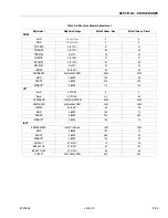
Page 39: ...0 30 LOMAX 35to65 50 50 ENGINESPD 2800to3800RPM 3600 3000 GAIN 0to999 180 50 DROOP 0to999 200 250 STABILITY 0to999 170 125 LIFT Accel 0 2TO5 0 4 4 Decel 0 2TO5 0 0 5 0 5 UPMINENG 1400TO2200RPM 2000 2000 UPMAXENG 2600to3600RPM 3000 3000 LOMAX 35to55 50 50 GAIN 0to999 150 10 DROOP 0to999 220 240 STABILITY 0to999 125 70 IDLE ENGINESPEED 1200TO1500rpm 1500 1500 GAIN 0to999 150 10 DROOP 0to999 250 85 S...

Page 40: ...n to default values Table 2 5 Machine Configuration Programming Information ConfigurationDigit Number Description DefaultNum ber 1 Model 1 2 3 260CRT 330CRT 400CRT 0 2 EngineSelection 0 1 2 750DualFuel 905Diesel 1105Diesel 0 3 Tilt 0 1 NoCutout Cutoutliftupanddriveiftiltedandelevated RequiredforAUSandBRZmarkets 0 4 DriveCutout 0 1 Nodrivecutoutswitchinstalled Cutsoutdrivewhendeckiselevatedaboveapr...

Page 41: ...hat a complete annual inspection be performed in accordance with the Annual Machine Inspection Report form Forms are supplied with each new machine and are also available from JLG Customer Service Form must be completed and returned to JLG Industries IMPORT ANT JLG INDUSTRIES REQUIRES THAT A COMPLETE ANNUAL INSPECTION BE PERFORMED IN ACCORDANCE WITH THE ANNUAL MACHINE INSPECTION REPORT FORM NOTE T...

Page 42: ...ump 1 5 7 Valves 1 5 8 HydraulicFilter SeeLubricationChart 5 14 9 HydraulicHosesandTubing 1 5 10 HydraulicOilTank 3 5 4 11 HydraulicTankBreather 6 14 12 FuelTank 3 5 4 13 LiftCylinder 1 12 5 6 13 4 14 LimitSwitch 1 7 15 TiltAlarmSwitch 1 7 16 PlacardsandDecals 1 2 17 WheelandTireAssemblies 1 8 9 18 DriveMotors 1 5 6 19 DriveBrakes 1 6 8 20 DriveTorqueHubs 1 3 5 6 21 SteerCylinder 1 5 6 13 4 22 Ste...

Page 43: ...hor ough knowledge of the equipment and related systems It should be recognized that the majority of the problems arising in the machine will be centered in the hydraulic and electrical systems For this reason every effort has been made to ensure that all likely problems in these areas are given the fullest possible treatment In the remaining machine groups only those problems which have more than...

Page 44: ...l valve not functioning properly Repair or replace valve Lift cylinder not functioning properly Repair or replace lift cylinder Enginedoesnotrespondwhenliftcontrol switch is moved to up position Refer to Electrical System Troubleshoot ing No response to control switch Noelectricalsignalbeingsenttoliftupcontrolvalve cartridge RefertoElectricalSystemTroubleshooting No responsetocontrolswitch Platfor...

Page 45: ...ing properly Repair or replace lift cylinder Platform drifts down Manual lowering valve not functioning properly Repair or replace valve Worn seals in lift cylinder Replace seals Holding valve on lift cylinder not function ing properly Repair or replace valve High Drive does not operate below horizontal Damaged wiring on limit switch Repair or replace wiring Damaged limit switch Replace limit swit...

Page 46: ... on controller improperly adjusted Adjust microswitch on controller for proper operation Machine will not travel forward Joystick not activated within three sec onds after drive switch is activated Activate drive switch then activate joy stick within three seconds Hydraulic system oil low Replenish oil as necessary Restricted or broken hydraulic line or fit ting Clean repair or replace line or fit...

Page 47: ...pair or replace wires as necessary High speed limit switch not functioning properly Repair or replace limit switch Loose or damaged wiring in valve wiring harness Ensure proper connection of wires at ter minal strip Using suitable test meter per form continuity test on wires Repair or replace wires as necessary SteeringSystem No response to steer control switch on controller Steer switch on contro...

Page 48: ...ires Repair or replace wires as neces sary Solenoid valve not functioning properly Repair or replace valve Restricted or broken hydraulic line on valve bank or hydraulic pump Clean repair or replace line Relief valve improperly set ornot function ing properly Reset repair or replace valve as neces sary Steer cylinder not functioning properly Repair or replace cylinder Machine will not steer left o...

Page 49: ...epairorreplaceline Machineoverloaded Checkweightinplatform Mainreliefvalvesettoohigh Resetvalveasrequired Hydraulicsystemoillow Replenishoilasnecessary Pumpnotdeliveringoil Restrictedsuctionline Cleanrepairorreplaceline Airenteringsystemthroughbrokenlineorfitting suctionside Replaceorrepairlineorfitting Oilleveltoolow Replenishoiltoproperlevel Pluggedstrainerintank Cleanstrainer Pumpcouplingdefect...

Page 50: ...undselectswitchnotpositioned properly Placeswitchtoplatformorground asnecessary Circuitbreakeropen Determineandcorrectcause Resetcircuit breaker Novoltagepresentatemergencystopswitch Checkbatterycablefrombatterytoemergency stopswitchforproperconnectionordamage Repairorreplacecableasnecessary Emergencystopswitchnotfunctioningproperly Replaceswitch Novoltagesuppliedtostartrelayfromemergency stopswit...

Page 51: ...yconnections Usingatestmeter checkrelaycoilterminalsfor presenceofelectricalpowerandforenergization ofrelaycoil Alsocheckrelayterminalsforcorrect switchingofcontacts Replacerelayasnecessary Malfunctioningstartersolenoidormotor Replacesolenoidormotorinaccordancewith applicablemanufacturer smanual Defectivestartlockoutsolenoid Replacestartlockoutsolenoid Malfunctioningignitionswitch Usingatestmeter ...

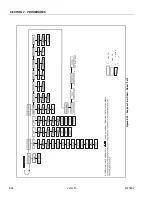
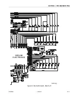
Page 52: ...SECTION 3 TROUBLESHOOTING 3 10 JLG Lift 3121804 GROUND ELECTRONICS Figure 3 1 Electrical Schematic Sheet 1 of 2 ...

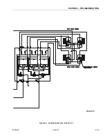
Page 53: ...SECTION 3 TROUBLESHOOTING 3121804 JLG Lift 3 11 GROUND ELECTRONICS 1870118_I Figure 3 2 Electrical Schematic Sheet 2 of 2 ...

Page 54: ...SECTION 3 TROUBLESHOOTING 3 12 JLG Lift 3121804 Figure 3 3 Hydraulic Schematic Sheet 1 of 2 ...

Page 55: ...SECTION 3 TROUBLESHOOTING 3121804 JLG Lift 3 13 2792397 E Figure 3 4 Hydraulic Schematic Sheet 2 of 2 ...

Page 56: ...SECTION 3 TROUBLESHOOTING 3 14 JLG Lift 3121804 This page intentionally left blank ...

Page 57: ......

Page 58: ...enson 80 Suite 71 13092 310 Campinas SP Brazil Phone 55 19 3295 0407 Fax 55 19 3295 1025 JLG Europe B V Jupiterstraat 234 2132 HJ Foofddorp The Netherlands Phone 31 23 565 5665 Fax 31 23 557 2493 JLG Industries Norge AS Sofeimyrveien 12 N 1412 Sofienyr Norway Phone 47 6682 2000 Fax 47 6682 2001 JLG Polska UI Krolewska 00 060 Warsawa Poland Phone 48 91 4320 245 Fax 48 91 4358 200 JLG Industries Eur...

Reviews: