SECTION 2 - PROCEDURES
2-2
– JLG Lift –
3121804
3.
If a bearing is found to be serviceable, apply a light
coat of oil and wrap it in clean (waxed) paper. Do not
unwrap reusable or new bearings until they are
ready to install.
4.
Lubricate new or used serviceable bearings before
installation. When pressing a bearing into a retainer
or bore, apply pressure to the outer race. If the bear-
ing is to be installed on a shaft, apply pressure to the
inner race.
Gaskets
Check that holes in gaskets align with openings in the
mating parts. If it becomes necessary to hand-fabricate a
gasket, use gasket material or stock of equivalent material
and thickness. Be sure to cut holes in the right location, as
blank gaskets can cause serious system damage.
Bolt Usage and Torque Application
1.
Use bolts of proper length. A bolt which is too long
will bottom before the head is tight against its related
part. If a bolt is too short, there will not be enough
thread area to engage and hold the part properly.
When replacing bolts, use only those having the
same specifications of the original, or one which is
equivalent.
2.
Unless specific torque requirements are given within
the text, standard torque values should be used on
heat-treated bolts, studs, and steel nuts, in accor-
dance with recommended shop practices.
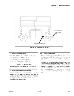
Hydraulic Lines and Electrical Wiring
Clearly mark or tag hydraulic lines and electrical wiring, as
well as their receptacles, when disconnecting or removing
them from the unit. This will assure that they are correctly
reinstalled.
Hydraulic System
1.
Keep the system clean. If evidence of metal or rub-
ber particles is found in the hydraulic system, drain
and flush the entire system.
2.
Disassemble and reassemble parts on clean work
surface. Clean all metal parts with non-flammable
cleaning solvent. Lubricate components, as
required, to aid assembly.
Lubrication
Service applicable components with the amount, type,
and grade of lubricant recommended in this manual, at
the specified intervals. When recommended lubricants are
not available, consult your local supplier for an equivalent
that meets or exceeds the specifications listed.
Batteries
Clean batteries, using a non-metallic brush and a solution
of baking soda and water. Rinse with clean water. After
cleaning, thoroughly dry batteries and coat terminals with
an anti-corrosion compound.
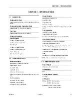
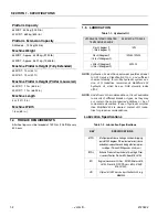
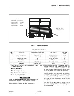
Lubrication and Servicing
Components and assemblies requiring lubrication and
servicing are shown in Section 1.
2.3
LUBRICATION INFORMATION
Hydraulic System
1.
The primary enemy of a hydraulic system is contam-
ination. Contaminants enter the system by various
means, e.g., using inadequate hydraulic oil, allowing
moisture, grease, filings, sealing components, sand,
etc., to enter when performing maintenance, or by
permitting the pump to cavitate due to insufficient
system warm-up or leaks in the pump supply (suc-
tion) lines.
2.
The design and manufacturing tolerances of the
component working parts are very close, therefore,
even the smallest amount of dirt or foreign matter
entering a system can cause wear or damage to the
components and generally results in faulty opera-
tion. Every precaution must be taken to keep
hydraulic oil clean, including reserve oil in storage.
Hydraulic system filters should be checked,
cleaned, and/or replaced as necessary, at the speci-
fied intervals required in the Lubrication Chart in
Section 1 and the Preventive Maintenance and
Inspection Chart in this section. Always examine fil-
ters for evidence of metal particles.
3.
Cloudy oils indicate a high moisture content which
permits organic growth, resulting in oxidation or cor-
rosion. If this condition occurs, the system must be
drained, flushed, and refilled with clean oil.
4.
It is not advisable to mix oils of different brands or
types, except as recommended, as they may not
contain the same required additives or be of compa-
rable viscosities. Good grade mineral oils, with vis-
cosities suited to the ambient temperatures in which
the machine is operating, are recommended for use.
NOTE: Metal particles may appear in the oil or filters of new
machines due to the wear-in of meshing compo-
nents.
Summary of Contents for 330CRT
Page 1: ...Service Maintenance Manual Model 330CRT 400CRT 3121804 April 7 2004 ...
Page 2: ......
Page 8: ...TABLE OF CONTENTS iv JLG Lift 3121804 This page left blank intentionally ...
Page 12: ...SECTION 1 SPECIFICATIONS 1 4 JLG Lift 3121804 Figure 1 1 Torque Chart ...
Page 22: ...SECTION 2 PROCEDURES 2 8 JLG Lift 3121804 Figure 2 3 400CRT LIft Cylinder ...
Page 54: ...SECTION 3 TROUBLESHOOTING 3 12 JLG Lift 3121804 Figure 3 3 Hydraulic Schematic Sheet 1 of 2 ...
Page 56: ...SECTION 3 TROUBLESHOOTING 3 14 JLG Lift 3121804 This page intentionally left blank ...
Page 57: ......


