SECTION 1 - SPECIFICATIONS
1-6
– JLG Lift –
3121804
1.9
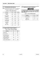
CYLINDER SPECIFICATIONS
NOTE: All dimensions are given in inches (in), with the met-
ric equivalent, centimeters (cm), in parentheses.
1.10 MAJOR COMPONENT WEIGHTS
1.11 CRITICAL STABILITY WEIGHTS
DO NOT REPLACE ITEMS CRITICAL TO STABILITY WITH ITEMS
OF DIFFERENT WEIGHT OR SPECIFICATION (FOR EXAMPLE:
FILLED TIRES, ENGINE) DO NOT MODIFY UNIT IN ANY WAY TO
AFFECT STABILITY.
Table 1-4. Cylinder Specifications
Description
Bore
Stroke
Rod Dia
Lift Cylinder
(330CRT)
4.0
(10.2)
63.7
(161.8)
2.75
(7.0)
Upper Lift Cylinder
(400CRT)
3.0
(7.62)
58.1
(147.6)
2.75
(7.0)
Lower Lift Cylinder
(400CRT)
4.0
(10.2)
58.1
(147.6)
2.75
(7.0)
Lockout Cylinder
(Oscillating Axle)
3.0
(7.6)
3.75
(9.5)
1.25
(3.2)
Leveling Jack
Cylinder
2.0
(5.1)
14.0
(35.6)
1.25
(3.2)
Steer Cylinder
2.5
(6.4)
7.1
(18.1)
1.25
(3.2)
Table 1-5. Major Component Weights
Component
Lb
Kg
Fixed Platform
569
258
Platform Extension
230
104
Arm Assembly- 330CRT
(Includes Lift Cylinder)
3200
1452
Arm Assembly- 400CRT
(Includes Lift Cylinder)
3900
1769
Chassis with Foam Filled Tires
4980
2259
Table 1-6. Critical Stability Weights
Component
Lb
Kg
Tires (Balasted Only)
246
111
Engine (Gas)
136
62
Engine (Diesel)
93
42
Summary of Contents for 330CRT
Page 1: ...Service Maintenance Manual Model 330CRT 400CRT 3121804 April 7 2004 ...
Page 2: ......
Page 8: ...TABLE OF CONTENTS iv JLG Lift 3121804 This page left blank intentionally ...
Page 12: ...SECTION 1 SPECIFICATIONS 1 4 JLG Lift 3121804 Figure 1 1 Torque Chart ...
Page 22: ...SECTION 2 PROCEDURES 2 8 JLG Lift 3121804 Figure 2 3 400CRT LIft Cylinder ...
Page 54: ...SECTION 3 TROUBLESHOOTING 3 12 JLG Lift 3121804 Figure 3 3 Hydraulic Schematic Sheet 1 of 2 ...
Page 56: ...SECTION 3 TROUBLESHOOTING 3 14 JLG Lift 3121804 This page intentionally left blank ...
Page 57: ......


