SECTION 2 - PROCEDURES
3121804
– JLG Lift –
2-19
Diesel Engine
NOTE: Never run the fuel tank dry. Diesel engines cannot
be restarted after running out of fuel until the fuel
system has been air-vented or ‘bled’ of air. See the
Kubota Instruction Manual for the proper procedure.
2.17 ELECTRONIC CONTROL SYSTEM
To Connect the Hand Held Analyzer:
1.
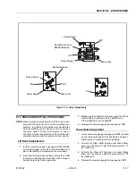
Connect the four pin end of the cable supplied with
the analyzer, to the top connection of the motor con-
troller and connect the remaining end of the cable to
the analyzer.
NOTE: The cable has a four pin connector at each end of
the cable; the cable cannot be connected back-
wards.
2.
Power up the Control System by turning the lower
key to the platform position and pulling both emer-
gency stop buttons on.
Using the Analyzer:
With the machine power on and the analyzer connected
properly, the analyzer will display the following:
HELP:
PRESS ENTER
At this point, using the
RIGHT
and
LEFT
arrow keys, you
can move between the top level menu items. To select a
displayed menu item, press
ENTER.
To cancel a selected
menu item, press
ESC
; then you will be able to scroll
using the right and left arrow keys to select a different
menu item.
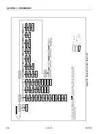
The top level menus are as follows:
HELP
DIAGNOSTICS
ACTIVATE TESTS
ACCESS LEVEL
PERSONALITIES
MACHINE SETUP
LEVEL VEHICLE
If you press
ENTER
, at the HELP:PRESS ENTER display,
and a fault is present during power up, the analyzer dis-
play will scroll the fault across the screen. If there was no
fault detected during power up, the display will read:
HELP: EVERYTHING OK
If
ENTER
is pressed again, the display moves to the fol-
lowing display:
LOGGED HELP
1: STARTUP (2/1)
At this point, the analyzer will display the current fault, if
any are present. You may scroll through the fault logs to
view what the last fifteen faults were. Use the right and left
arrow keys to scroll through the fault logs. To return to the
beginning, press
ESC
two times.
When a top level menu is selected, a new set of menu
items may be offered; for example:
PLATFORM
DRIVE
LIFT SEL
SPEED SEL
HORN
ENGINE START
FUEL/GLOW
STEER LEFT
STEER RIGHT
JOYSTICK
Pressing
ENTER
with any of the above displayed menus,
will display additional sub-menus within the selected
menu. In some cases the next level is the parameter or
information to be changed. Refer to the flow chart for what
menus are available within the top level menus. You may
only view the personality settings for selected menus
while in access level 2. Remember, you may always can-
cel a selected menu item by pressing the
ESC
key.
Summary of Contents for 330CRT
Page 1: ...Service Maintenance Manual Model 330CRT 400CRT 3121804 April 7 2004 ...
Page 2: ......
Page 8: ...TABLE OF CONTENTS iv JLG Lift 3121804 This page left blank intentionally ...
Page 12: ...SECTION 1 SPECIFICATIONS 1 4 JLG Lift 3121804 Figure 1 1 Torque Chart ...
Page 22: ...SECTION 2 PROCEDURES 2 8 JLG Lift 3121804 Figure 2 3 400CRT LIft Cylinder ...
Page 54: ...SECTION 3 TROUBLESHOOTING 3 12 JLG Lift 3121804 Figure 3 3 Hydraulic Schematic Sheet 1 of 2 ...
Page 56: ...SECTION 3 TROUBLESHOOTING 3 14 JLG Lift 3121804 This page intentionally left blank ...
Page 57: ......

