SECTION 3 - TROUBLESHOOTING
3-4
– JLG Lift –
3121804
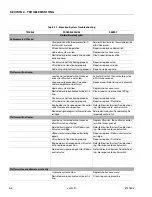
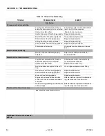
Table 3-2. Chassis Troubleshooting
TROUBLE
PROBABLE CAUSE
REMEDY
Drive System
No response to drive controller
Joystick not activated within three sec-
onds after drive select switch is activated.
Activate drive select switch, then activate
joystick within three seconds.
Hydraulic system oil low.
Replenish oil as necessary.
Hydraulic pump not functioning properly. Repair or replace pump.
Restricted or broken pump supply line.
Clean, repair or replace line.
Drive motor not functioning properly.
Repair or replace motor.
Damaged wiring on drive controller.
Repair or replace wiring.
Drive controller not functioning properly.
Repair or replace controller.
Drive brake not releasing.
Determine cause and repair or replace
brake.
Machine drives erratically
Microcircuit on controller improperly
adjusted.
Adjust microswitch on controller for
proper operation.
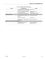
Machine will not travel forward
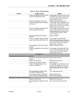
Joystick not activated within three sec-
onds after drive switch is activated.
Activate drive switch, then activate joy-
stick within three seconds.
Hydraulic system oil low.
Replenish oil as necessary.
Restricted or broken hydraulic line or fit-
ting.
Clean, repair or replace line or fitting.
Control valve not functioning properly.
Repair or replace valve.
Drive motor not functioning properly.
Repair or replace motor.
Brake not functioning properly.
Repair or replace brake.
Engine will not respond when enable
switch is activated and drive controller is
activated.
Refer to Electrical System Troubleshoot-
ing - No response to control switch.
No electrical signal being sent to the drive
valve cartridge.
Refer to Electrical System Troubleshoot-
ing - No response to control switch.
Machine will not travel in reverse
See: Machine will not travel forward.
High-Speed Drive function does not
operate
Summary of Contents for 330CRT
Page 1: ...Service Maintenance Manual Model 330CRT 400CRT 3121804 April 7 2004 ...
Page 2: ......
Page 8: ...TABLE OF CONTENTS iv JLG Lift 3121804 This page left blank intentionally ...
Page 12: ...SECTION 1 SPECIFICATIONS 1 4 JLG Lift 3121804 Figure 1 1 Torque Chart ...
Page 22: ...SECTION 2 PROCEDURES 2 8 JLG Lift 3121804 Figure 2 3 400CRT LIft Cylinder ...
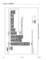
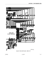
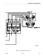
Page 54: ...SECTION 3 TROUBLESHOOTING 3 12 JLG Lift 3121804 Figure 3 3 Hydraulic Schematic Sheet 1 of 2 ...
Page 56: ...SECTION 3 TROUBLESHOOTING 3 14 JLG Lift 3121804 This page intentionally left blank ...
Page 57: ......


