Section 2.
System Description
ATTENTION INSTALLER:
Various application notes (including more detailed
instructions) are available from the Dealer covering installation, operation,
maintenance, and plumbing of the chlorinator system.
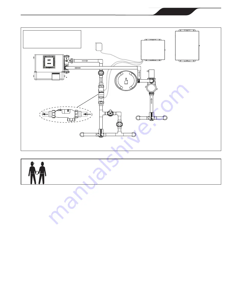
Figure 1.
Typical AquaPure
and
PureLink Installation Example With Options
Pump
Filter
PureLink
Power Center
Cell with
Flow/Temp/Salinity Sensor
Heater
Spa Intake
Pool Intake
Spa Return
Pool Return
Options List
1. ORP/External Control Interface
2. ORP/Freeze Control Unit
3. Heater
ORP Unit
(Control Signal from ORP Unit to
ORP Interface/Aux Board)
2.1 Product Description
The AquaPure and PureLink systems use a process known as electrolysis to produce sodium hypochlorite
(liquid chlorine) from a low concentration of salt added to the pool water. Hypochlorite kills bacteria,
oxidizes organic material, and kills algae then reverts back to salt. The system then reuses the salt and the
process starts over again. The systems are comprised of the following components:
AquaPure
Control Center
(for stand
alone systems)
• The AquaPure control center converts AC power into low voltage DC current
which is required by the cell to perform the electrolysis.
• The LCD display on the user interface offers monitoring of chlorine production,
cell modes, salinity level, temperature, water flow and diagnostics.
• The control center is connected with the pool circulation pump electrical source so
that the electrolytic cell can only operate when the pool pump is on. An optional
pool pump timer can be utilized to help control this function. The flow portion of
the Flow/Temp/Salinity Sensor is a backup device only.
AquaPure®
Control
Center
OR
Page 7
ENGLISH
Page 7
ENGLISH
Jandy
®
AquaPure
®
/PureLink™ Power Center and Cell Kit
|
Installation and Operation Manual


